Replacement
Part 1 Of 2:
Part 2 Of 2:
REMOVAL
1. Drain the differential oil.
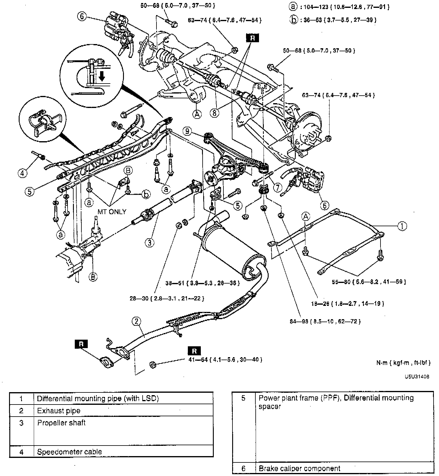
2. Remove in the order indicated in the illustration, referring to the following notes:
Propeller Shaft (3)
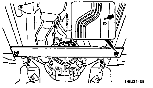
1. Before removing the propeller shaft, mark the flanges for correct installation.
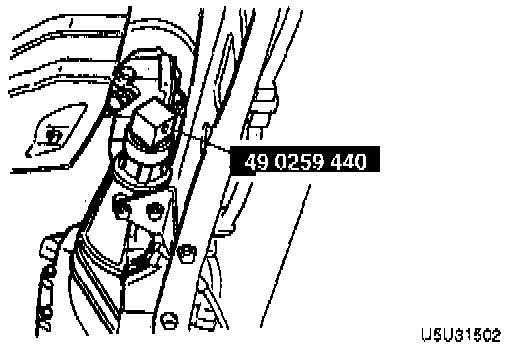
2. Remove the propeller shaft from the extension housing, and immediately install the Special Service Tool (SST) to prevent oil leakage.
Power Plant Frame (PPF) (5)
1. Disconnect the wire harness from the Power Plant Frame (PPF).

2. Support the transmission with a jack.

3. Remove the PPF bracket.

4. Remove the differential-side bolts, and pry out the spacer.

5. Remove the differential mounting spacer.
CAUTION: Removing the PPF spacers will reduce the performance of the PPF. If the spacers are removed, replace the PPF as an assembly.

6. Remove the transmission-side bolts, and remove the PPF.
NOTE: If the sleeve can not removed easily, tap the side of sleeve with a plastic hammer.
7. Remove the sleeve.
Drive Shaft (8)
NOTE: If the drive shaft will not come out of the rear hub support easily, install a discarded nut onto the drive shaft so that the nut is flush with the end of the drive shaft. Tap the nut with a copper hammer to loosen the drive shaft from the wheel hub.
1. Pull the rear hub support from the drive shaft.
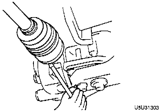
2. Remove the drive shaft from the differential by using a pry bar.
Differential (9)
1. Separate the driveshaft from the differential.
2. Support the differential by using a jack.
3. Lower the differential and move it forward.
4. To prevent damaging the fire wall, crank angle sensor, and engine mount, support the transmission as follows:
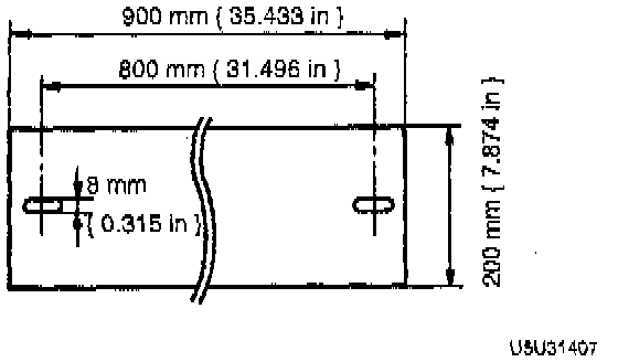
a. Prepare a steel plate (as shown in the illustration), a wooden block, bolts (M8 x 1.25), and washers.
b. Install the parts as shown in the illustration.
INSPECTION
Propeller Shaft (3)
CAUTION: Cleaning sealed bearings with cleaning fluids or a steam cleaner can wash the grease out of the bearing.
1. Clean the propeller shaft (except for the universal joint) with a steam cleaner or solvent.
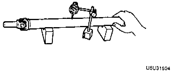
2. Measure the propeller shaft runout by using a dial indicator. Replace the propeller shaft if runout is excessive. Maximum runout is 0.4 mm (0.016 inch).
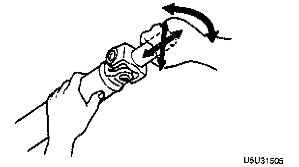
3. Move the universal joints in the directions shown, and check for universal joint looseness. If there is looseness, replace the propeller shaft.
4. Check operation of the universal joint. If the universal joint has excessive resistance, replace the propeller shaft.
INSTALLATION
A. Install in the reverse order of removal indicated in the table, referring to the following notes:
Drive Shaft (8)
1. Install a new clip onto the drive shaft.
2. Measure the outer diameter of the clip after installing, and replace the clip if it exceeds the specification.
CAUTION: The sharp edges of the drive shaft snap ring can slice or puncture the oil seal. Be careful when installing the drive shaft to the transmission.
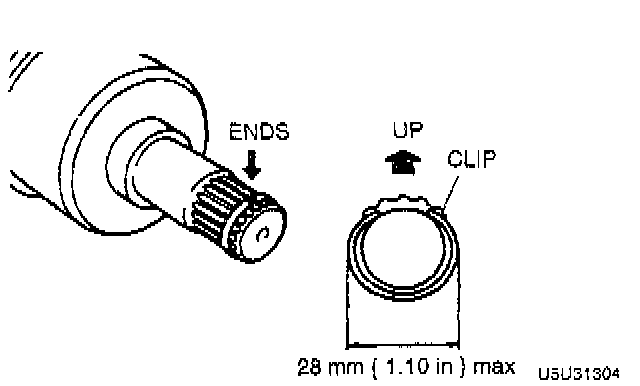
3. With the ends of the clip facing upward, push the drive shaft into the differential.
4. After installation, pull outward on the double offset joint outer ring and verify that the drive shaft is securely held by the clip.

Power Plant Frame (PPF) (5)
1. Install the differential mounting spacer and tighten to 38 - 51 Nm (28 - 38 ft. lbs.).
2. Support the transmission with a jack so that it is level.

3. Position the PPF and install the sleeve.
4. Install the spacer and bolts and snugly tighten the reamer bolt. The reamer bolt should be installed in the forward hole.
5. Tighten the outer bolts snugly.

6. Tighten the bolts to 104 - 123 Nm (77 - 91 ft. lbs.) in the order shown.

7. Install the PPF bracket. Tightening torque:
^ A: 104 - 123 Nm (77 - 91 ft. lbs.).
^ B: 37 - 53 Nm (27 - 39 ft. lbs.).
8. Remove the jack, and connect the wire harness.

9. Measure distance A with a straightedge and vernier calipers.
10. If the distance A is not within 66.0 +/-5 mm (2.60 +/-0.197 inch), reposition the PPF to the transmission.
Propeller Shaft (3)
1. Align the marks, and install the propeller shaft. Tighten to 50 - 58 Nm (37 - 43 ft. lbs.).
2. Verify that there is no abnormal noise or vibration when driving the vehicle. If noise or vibration comes from the propeller shaft, replace the propeller shaft.
B. Add the specified oil to the specified level.
GRADE:
API Service GL-4 or GL-5
VISCOSITY:
Above -18°C (0°F) SAE 90
Below -18°C (0°F) SAE 80