Unit Repair
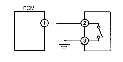
1. Measure the PCM #1 terminal voltage and confirm that it is 0V when the switch is on and B + when the switch is off.
- If the #1 terminal voltage and the NGS monitor voltage are the same, proceed to the next step.
- If there is a difference of 0.5V or more, check the following points concerning the PCM connector:
- Female terminal opening loose
- Coupler (pin holder) damage
- Pin discoloration (blackness)
- Harness/pin crimp is loose or disconnected
2. When the switch is off, measure the #2 sensor terminal voltage.
- If there is a 0.5V or more difference between the sensor and NGS voltages, check the harness for open or short circuits.
- If the sensor and NGS voltages are the same, check the following points concerning the sensor connector. If there are no problems, proceed to the next step.
- Female terminal opening loose
- Coupler (pin holder) damage
- Pin discoloration (blackness)
- Harness/pin crimp is loose or disconnected
3. Confirm that the #3 terminal switch voltage is at 0V
- If it is at 0V, proceed to the next step.
- If not, check the following points relating to the switch connector:
- Open circuit in harness
- Female terminal opening loose
- Coupler (pin holder) damage
- Pin discoloration (blackness)
- Harness/pin crimp is loose or disconnected.
4. Inspect the switch, referring to the workshop manual. If necessary, replace the switch.