Emissions/Electrical - MIL ON/DTC's P0443 or P0455 Set
01-016/032000 MPV
MIL ILLUMINATION DTC P0443 OR P0455
BULLETIN NOTE
This bulletin supersedes bulletin 01-026/02, issued 10/15/02. The NOTE under REPAIR PROCEDURE has been updated.
APPLICABLE MODEL(S)/VINS
2000 MPV with VINs lower than JM3 LW28** Y0 183838.
DESCRIPTION
Some vehicles may exhibit an open circuit in the purge solenoid valve harness near the purge solenoid valve connector and DTC P0443 or P0455 is stored in the PCM memory.
The following factors can cause an open circuit in the purge solenoid valve harness.
^ The harness may be too short.
^ The harness may be stretching due to engine torque motion.
^ The location where the purge solenoid harness is branched may be improper. The harness length has been increased to prevent this condition.
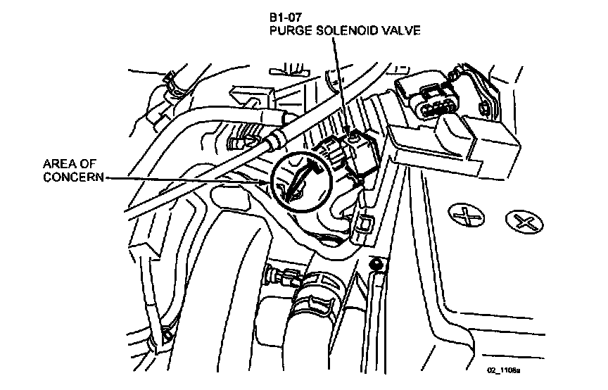
Customers having this concern should have their vehicle repaired using the following procedure.
REPAIR PROCEDURE
NOTE:
When you encounter this concern, refer to the 2000 MPV wiring Diagram and repair the vehicle using the Mazda Terminal Repair Kit (49L0-88-0A0A) to add additional wire to the harness. If the terminal needs to be replaced, look in drawer # )3 of the kit and use terminal part number 49L0-88-0A2-028.
1. Disconnect the harness connector of the purge solenoid valve.
2. Pull out the G/B and W/R wires from the connector.

3. Cut the pulled-out G/B wire at approximately 10 mm from the terminal. (If an open circuit location is already known, cut there.)

4. Add a 5 cm harness of the same thickness as the GIB wire, to the G/B wire. Solder the joints, and waterproof with butyl tape, then apply vinyl tape.
5. Same as Step 4, cut the pulled-out W/R wire at approximately 20 mm from the terminal. (If an open circuit location is already known, cut there.)
6. Add a 5 cm harness of the same thickness as the W/R wire, to the W/R wire. Solder the joints, and waterproof with butyl tape, then apply vinyl tape.

7. To avoid short circuit, be sure to set the joints at least 10 mm away from each other.
8. Install the G/B and W/R wires into the connector and connect it to the purge solenoid valve.
9. Verify repair.
WARRANTY INFORMATION
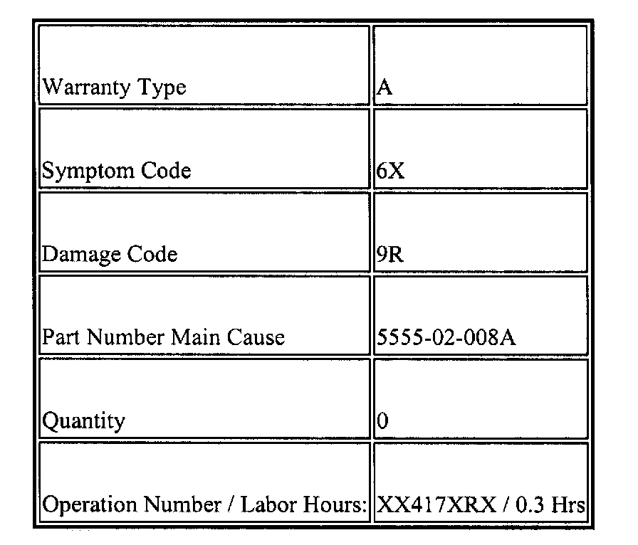
NOTE:
This information applies to verified customer complaints on vehicles covered under normal warranty. Refer to the SRT microfiche for warranty term information.