A/C - Temperature Difference Between Dash Vents
HVAC07-001/04
2000-2005 MPV - AIR TEMPERATURE OUTPUT
DIFFERENCE BETWEEN CENTER DASH VENTS
BULLETIN NOTE
This bulletin supersedes the previous bulletin issued on 02/12/04. The APPLICABLE MODEL(S)/VIN information has been revised.
APPLICABLE MODEL(S)/VINS
2000 - 2005 MPV
DESCRIPTION
On some vehicles, the output air temperature may differ between the two (2) center dash air vents (vents on either side of audio system). This condition usually occurs when the HVAC settings are in the following positions: A/C switch ON, in BI-LEVEL or VENT mode, Temperature Control Dial in 1:00 to 3:00 position (set for warm air).
Customers having this concern should have their vehicle repaired using the following repair procedure.
REPAIR PROCEDURE
Using the service "plate" and modifying the HVAC cooling/heating unit will decrease the output air temperature difference between the center dash vents.
1. Verify customer concern.
2. Record the customer's radio pre-set stations.
3. Remove the dashboard/cooling unit according to the MPV Workshop Manual (Section 07-11) FRONT A/C UNIT REMOVAL/INSTALLATION.
FRONT A/C COOLING UNIT MODIFICATION
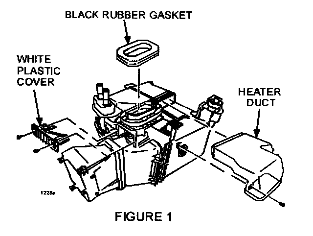
1. Set the cooling unit on a work bench with the heater pipes pointing upward and the white heater duct facing toward you as shown in FIGURE 1.
2. Remove one (1) screw holding the heater duct to the cooling unit, then remove the duct.
3. Carefully remove the black rubber gasket by peeling it off from the cooling unit.
NOTE:
Gasket will need to be reused. Do not allow any dirt or debris to contact the gasket adhesive.
4. Remove two (2) screws holding the white plastic cover near the expansion valve, then remove the cover.

5. Remove one (1) screw holding the small white plastic cover found on the opposite side, then remove the cover according to FIGURE 2.
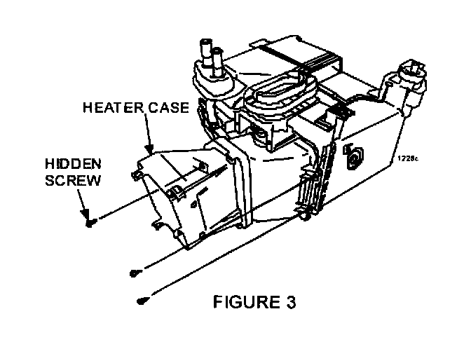
6. Remove three (3) screws holding the heater case, then remove the heater case according to FIGURE 3.
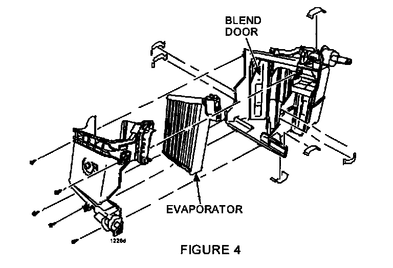
7. Position A/C cooling unit to remove five (5) screws and seven (7) small clips holding front evaporator cover according to FIGURE 4.
8. Pull evaporator cover off.
9. Remove the evaporator from the cooling unit and carefully set aside to prevent any damage to the evaporator cooling fins.
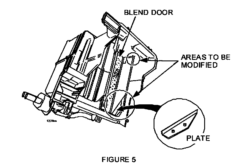
10. Prepare to install the "plate" and modify the "case rib" area shown in FIGURE 5.
11. Place shop rags under the blend door area.
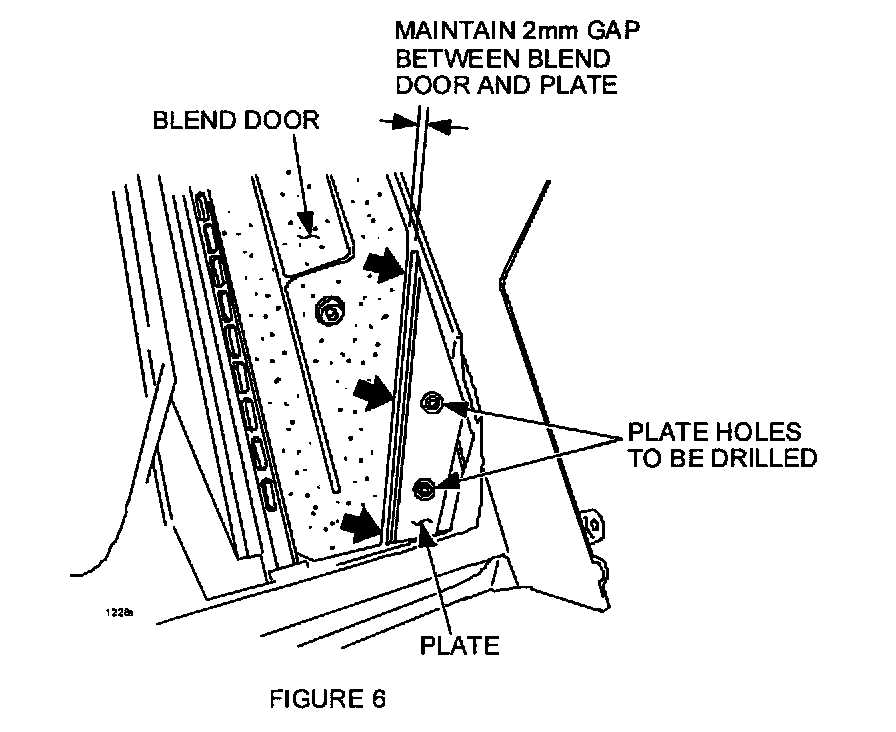
12. Close blend door and position plate so there is a 2 mm gap between the blend door and plate when the blend door is closed as shown in FIGURE 6.
13. Using the plate as a template, hold in position and mark the two (2) holes for drilling.
WARNING:
Be sure to wear safety glasses before drilling.
14. Drill two (2) holes using a 5/32" drill bit.
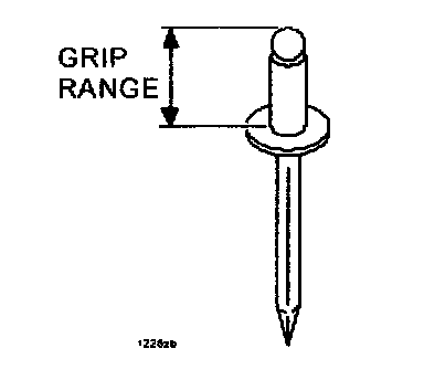
15. Attach the plate to the cooling unit case with two (2) 5/32" pop rivets with 13 mm "Grip Range."
16. Move the blend door back and forth to ensure the door is not binding on the plate.
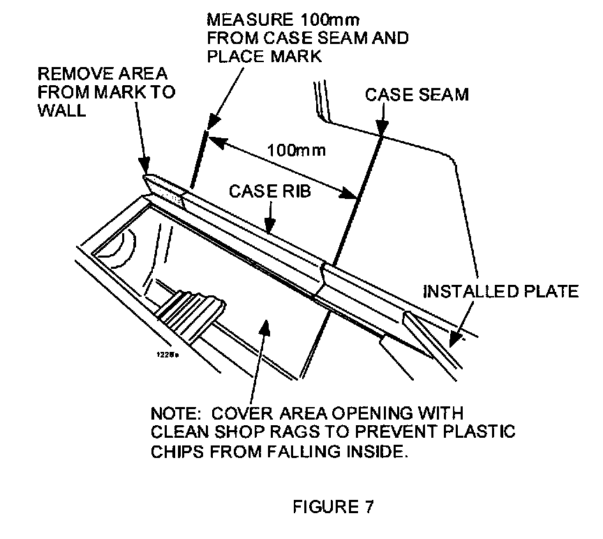
17. Using a dremel tool, die grinder, or hot knife, remove only the "shaded" portion of the case rib as shown in FIGURE 7.
18. Remove the case rib portion and shop rags.
19. Remove all plastic debris from under the blend door and inside the cooling unit with compressed air.
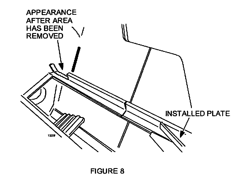
NOTE:
After the modifications have been completed, the cooling unit should appear as shown in FIGURE 8.
20. Re-assemble the cooling unit in reverse order.
21. Re-install cooling unit and dashboard assembly in the reverse order of removal.
22. Re-charge A/C system and confirm that all dashboard and HVAC controls operate properly.
23. Re-enter customer's radio pre-set stations.
24. Verify repair.
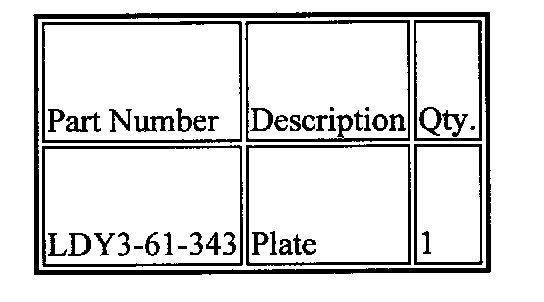
PART(S) INFORMATION
WARRANTY INFORMATION
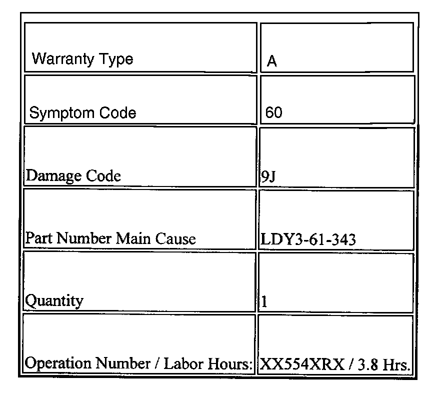
NOTE:
This warranty information applies only to verified customer complaints on vehicles eligible for warranty repair. Refer to the SRT microfiche for warranty term information.