Road Test Procedures
ROAD TESTRoad Test Preparation
1. Inspect the engine coolant.
2. Inspect the engine oil.
3. Inspect the ATF levels.
4. Inspect the idle speed and ignition timing in P position.
5. Bring up the engine and transaxle to normal operating temperature.
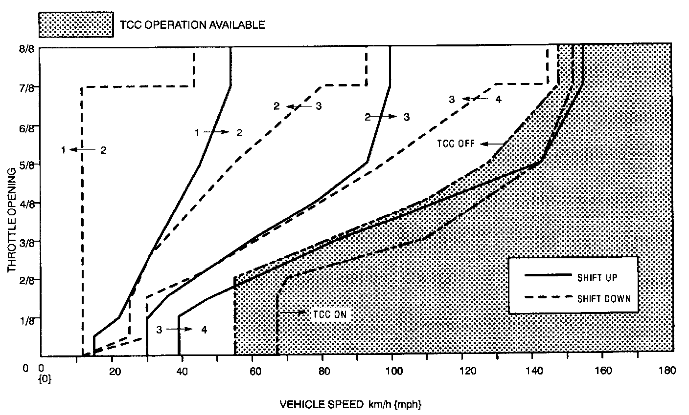
Typical Shift Diagram
D Range Test
1. Perform road test preparation.
D range (O/D OFF switch OFF)
Note The NORMAL mode and SLOPE mode are automatically selected by the PCM. The PCM shifts to SLOPE mode when the upgrade or downgrade is approximately 4 % or more, and shifts to NORMAL mode when the upgrade or downgrade is approximately 3 % or less.
1. Shift the selector lever to D range.
2. Accelerate the vehicle with half and WOT.
3. Verify that 1 -> 2, 2 -> 3, and 3 -> 4 upshifts and downshifts are obtained. The shift points must be as shown in the vehicle speed and shift point table.
- If not as specified, inspect the PCM and ATX.
4. Drive the vehicle in 4GR, 3GR, and 2GR and verify that kickdown occurs for 4 -> 3, 4 -> 2, 4 -> 1, 3 -> 2, 3 -> 1, 2 -> 1, and that the shift points are as shown in the table below.
- If not as specified, inspect the PCM and ATX.
5. Decelerate the vehicle and verify that engine braking effect is felt in 4GR and 3GR.
- If not as specified, inspect the PCM and ATX.
6. Drive the vehicle and verify that TCC operation is obtained. The operation points must be as shown in the vehicle speed and shift point table.
- If not as specified, inspect the PCM and ATX.
D range (O/D OFF switch ON)
1. Shift the selector lever to D range and select the O/D OFF switch ON.
2. Accelerate the vehicle with half and WOT.
3. Verify that 1 -> 2 and 2 -> 3 upshifts and downshifts are obtained. The shift points must be as shown in the vehicle speed and shift point table.
- If not as specified, inspect the PCM and ATX.
4. Drive the vehicle in 3GR and 2GR and verify that kickdown occurs for 3 -> 2, 3 -> 1, 2 -> 1, and that the shift points are as shown in the vehicle speed and shift point table.
- If not as specified, inspect the PCM and ATX.
5. Decelerate the vehicle and verify that engine braking effect is felt in 3GR.
- If not as specified, inspect the PCM and ATX.
6. Drive the vehicle and verify that TCC operation is obtained in 3GR. The operation points must be as shown in the vehicle speed and shift point table.
- If not as specified, inspect the PCM and ATX.
Noise and vibration
1. Drive the vehicle in 3GR (O/D OFF switch ON) and listen closely for any noise or vibration. The torque converter, drive shaft, and differential can be sources of noise and vibration if they are not functioning properly. Inspect these when searching for sources of noise and vibration.
Vehicle Speed And Shift Point Table
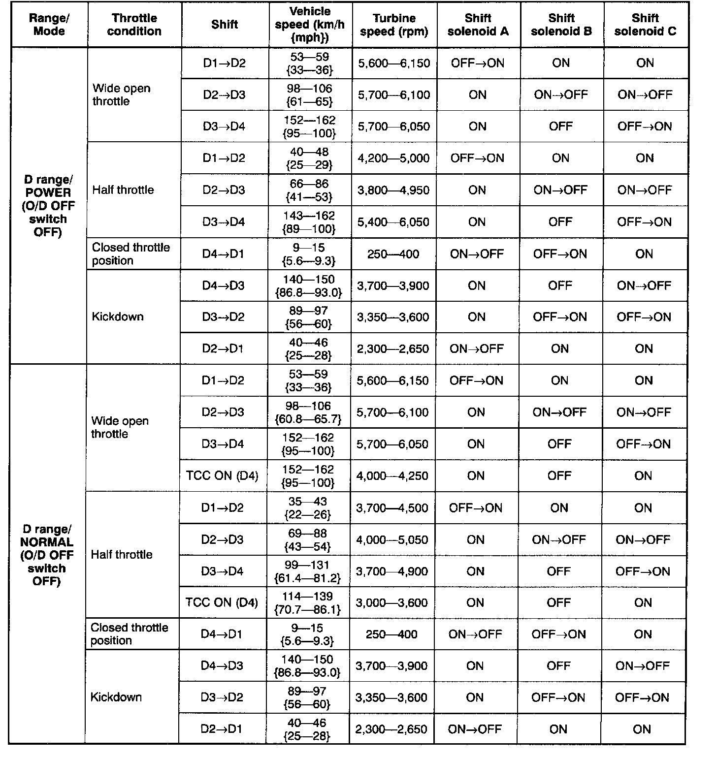
Part 1 of 3
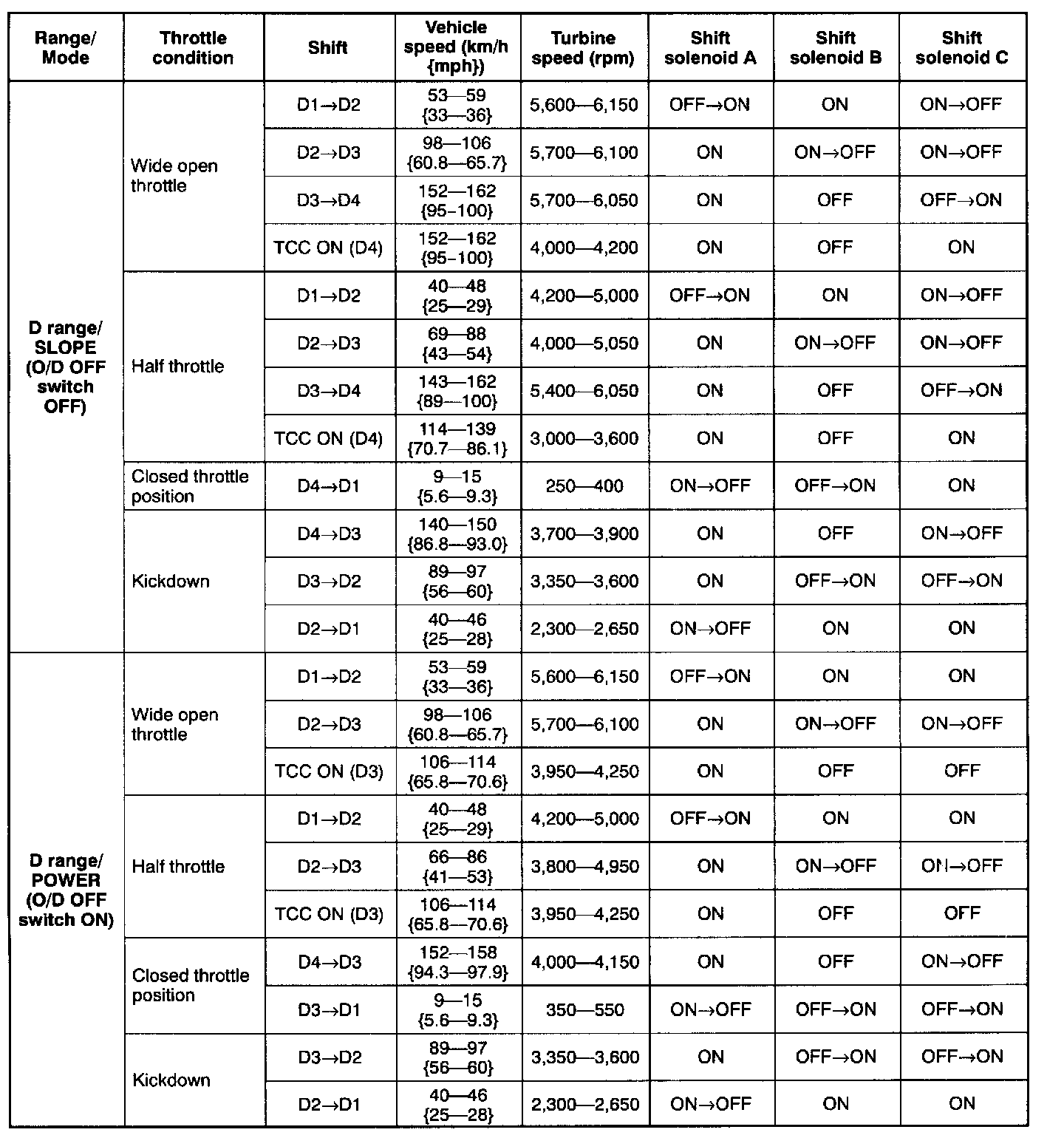
Part 2 of 3
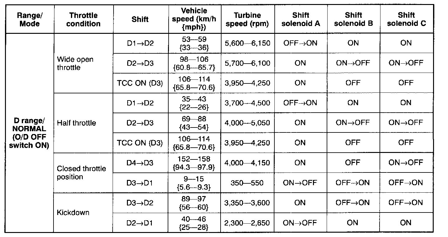
Part 3 of 3
Note The shift solenoid electrical ON-OFF pattern in this table describes the stabilized condition before and after shift control. The pattern may oscillate between ON and OFF momentarily while shifting-up or down.
2 Range Test
1. Perform road test preparation.
2. Shift the selector lever to 2 range.
3. Accelerate the vehicle with half and WOT, and verify that second gear is held.
- If not as specified, inspect the PCM and ATX.
4. Decelerate the vehicle and verify that engine braking effect is felt.
- If not as specified, inspect the PCM and ATX.
Noise and vibration
1. Drive the vehicle in 2GR and listen closely for any out of the ordinary noise or vibration. The torque converter, drive shaft, and differential can be sources of abnormal noise and vibration if they are not functioning properly. Inspect these when searching for sources of noise and vibration.

Shift Point
Note The shift solenoid electrical ON-OFF pattern in this table describes the stabilized condition before and after shift control. The pattern may oscillate between ON and OFF momentarily while shifting-up or down. This is normal.
1 Range Test
1. Perform road test preparation.
2. Shift the selector lever to 1 range.
3. Accelerate the vehicle with half and WOT, and verify that 1 GR is held.
- If not as specified, inspect the PCM and ATX.
4. Decelerate the vehicle and verify that engine braking effect is felt.
- If not as specified, inspect the PCM and ATX.
Noise and vibration
1. Drive the vehicle in 1 OR and listen closely for any out of the ordinary noise or vibration. The torque converter, drive shaft, and differential can be sources of abnormal noise and vibration if they are not functioning properly. Inspect these when searching for sources of noise and vibration.

Shift point
Note The shift solenoid electrical ON-OFF pattern in this table describes the stabilized condition before and after shift control. The pattern may oscillate between ON and OFF momentarily while shifting-up or down. This is normal.
P Position Test
1. Shift into P position on a gentle slope. Release the brake, and verify that the vehicle does not roll.
- If the vehicle rolls, inspect the ATX.
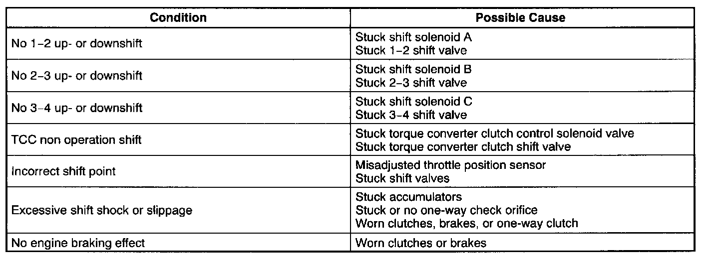
Evaluation