Timing Chain Disassembly/Assembly
TIMING CHAIN DISASSEMBLY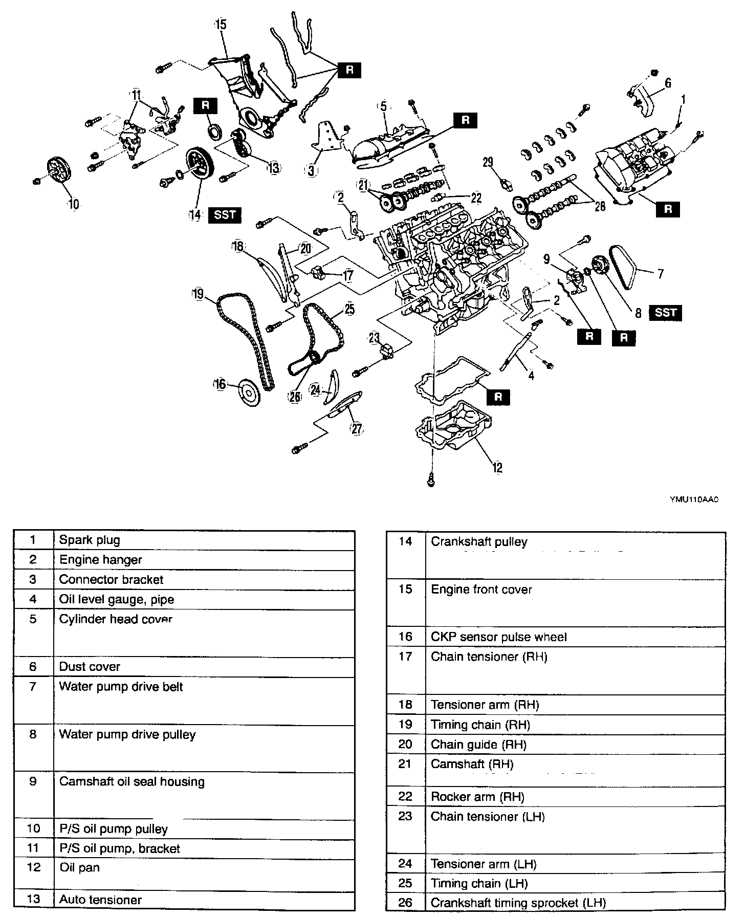
1. Disassemble in the order indicated in the table.
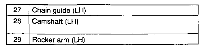
Cylinder Head Cover Disassembly Note
1. Remove the cylinder head cover bolts in the order indicated in the figure.
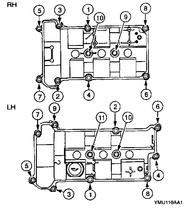
Water Pump Drive Belt Disassembly Note
1. Rotate the belt tensioner clockwise to release the drive belt tension and remove the belt.
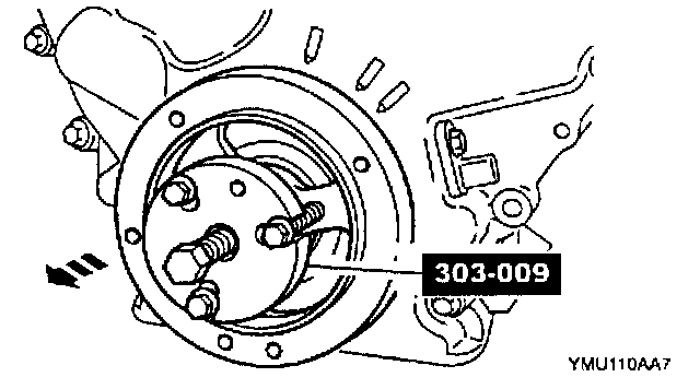
Water Pump Drive Pulley Disassembly Note
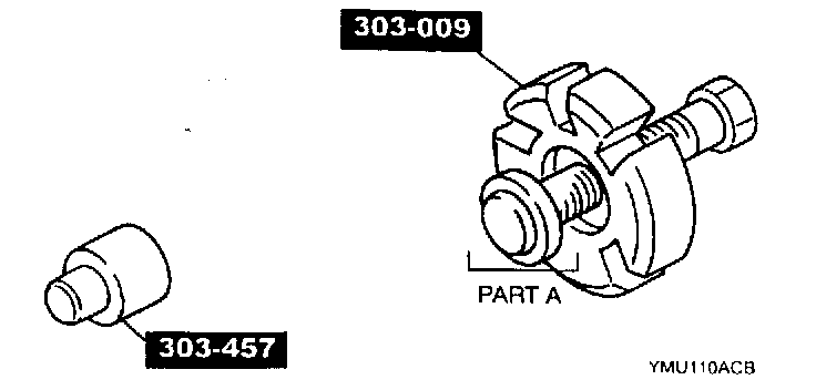
1. Replace part A of the SST (49 UN30 3009) with the SST (49 UN30 3457).
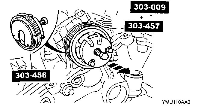
2. Remove the water pump pulley using the SST
Camshaft Oil Seal Housing Disassembly Note
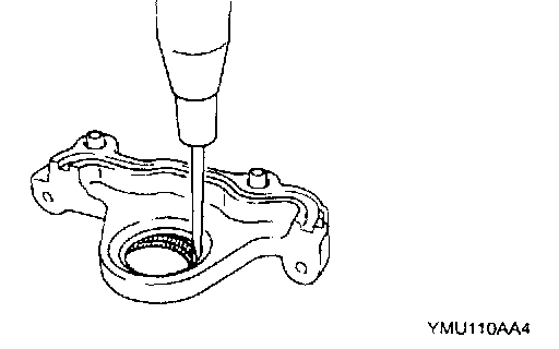
1. Remove the oil seal using a screwdriver.
Oil Pan Disassembly Note
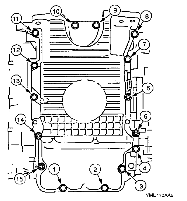
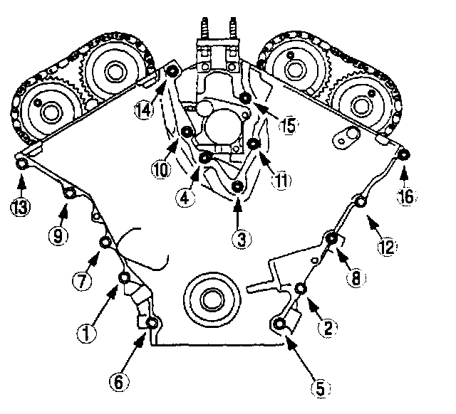
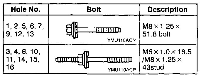
1. Remove the oil pan bolts and studs in the order indicated in the figure.
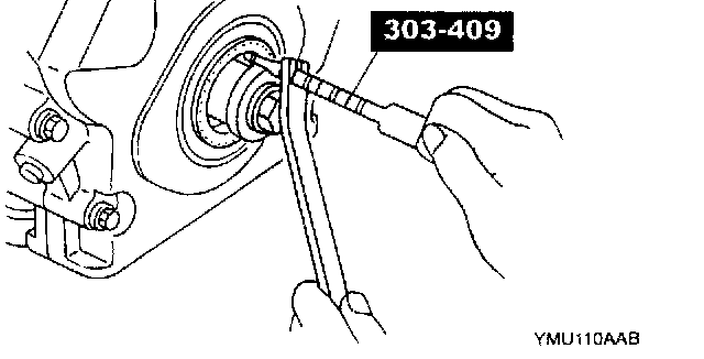
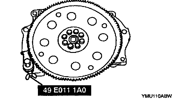
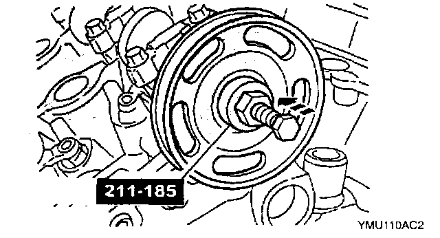
Crankshaft Pulley Disassembly Note
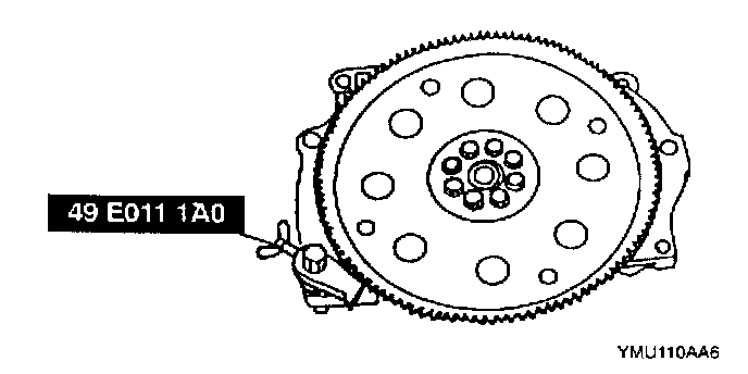
1. Hold the crankshaft using the SST
2. Remove the crankshaft pulley lock bolt.
3. Remove the crankshaft pulley using the SST.
Engine Front Cover Disassembly Note
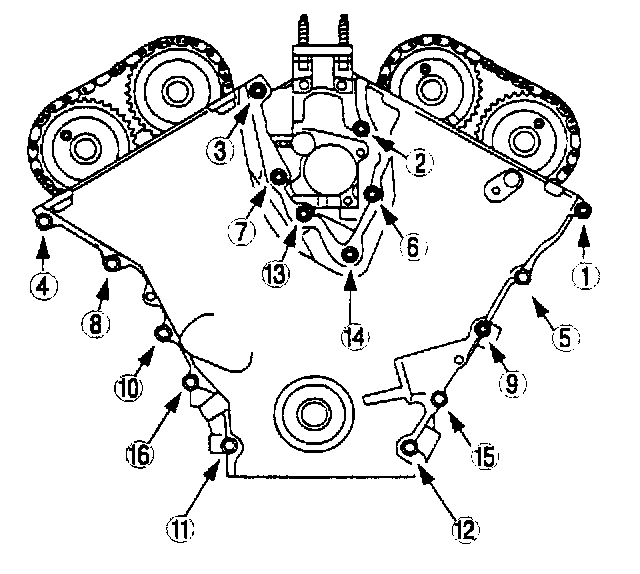
1. Remove the engine front cover bolts and studs in the order indicated in the figure.
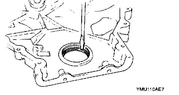
2. Remove the oil seal using a screwdriver.
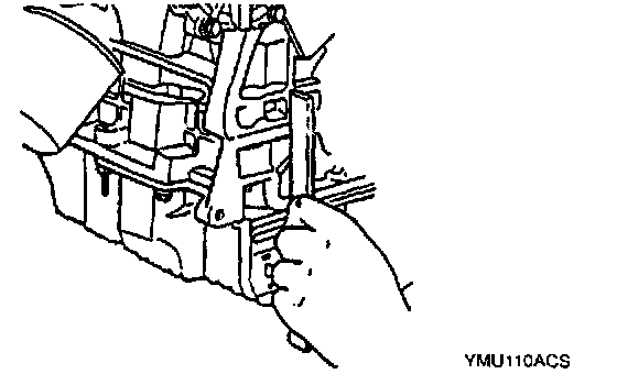
Chain Tensioner (RH) Disassembly Note
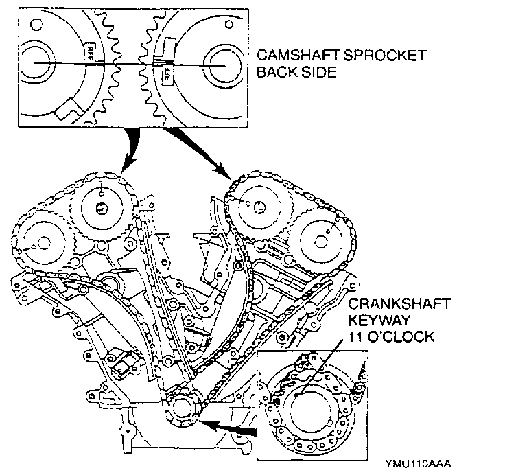
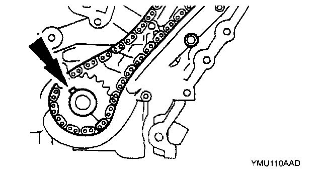
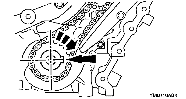
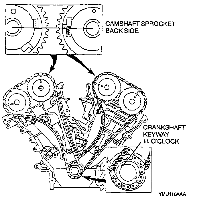
1. Before removing chain tensioner (RH), turn the crankshaft clockwise to position the crankshaft keyway in the 11 o'clock position.
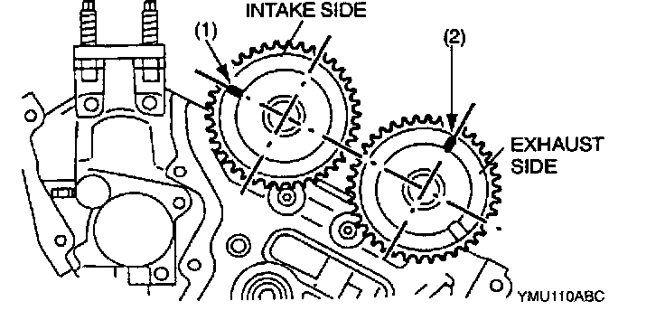
2. Verify that RFF marks on the camshaft sprockets are aligned.
3. Turn the crankshaft clockwise to position the crankshaft keyway in the 3 o'clock position. (camshafts (RH) are in the neutral position.)
4. Hold the timing chain tensioner ratchet lock mechanism away from the ratchet stem with a thin screwdriver.
5. Slowly press the tensioner piston.
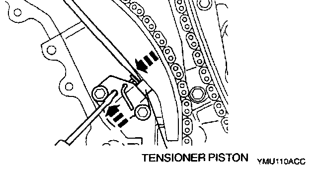
6. Hold the tensioner piston with a 1.5 mm (0.06 inch) wire or paper clip.
Camshaft (RH) Disassembly Note
1. Before removing the camshaft, inspect the following.
1. Camshaft end play
2. Camshaft journal oil clearance
Caution: Remove the camshaft bearing thrust caps 1R and 5R first. Do not loosen any of the other bolts until the thrust caps are removed, or damage; to the thrust caps may occur.
Note: The camshaft bearing caps are numbered to make sure they are assembled in their original positions. When removed, keep the bearing caps with the cylinder head they were removed from. Do not mix the caps.
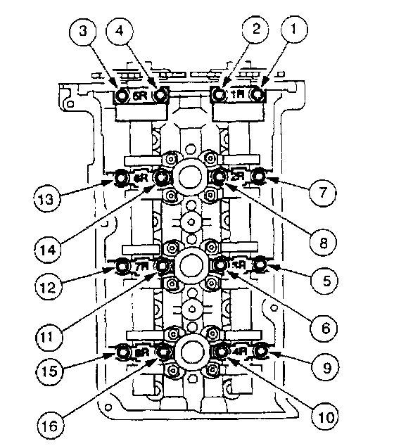
2. Remove the camshaft cap bolts in the order indicated in the figure in several passes.
Chain Tensioner (LH) Disassembly Note
1. Before removing chain tensioner (LH), turn the crankshaft clockwise 1 and 2/3 turns to position the crankshaft keyway in the 11 o'clock position. (camshafts (LH) are in the neutral position.)
2. Press and hold the tensioner piston by following Step 4 to 6 in Chain Tensioner (RH) Disassembly Note.
Camshaft (LH) Disassembly Note
1. Before removing the camshaft, inspect the following.
1. Camshaft end play
2. Camshaft journal oil clearance
Caution: Remove the camshaft bearing thrust caps 1R and 5R first. Do not loosen any of the other bolts until the thrust caps are removed, or damage to the thrust caps may occur.
Note: The camshaft bearing caps are numbered to make sure they are reassembled in their original position. When removed, keep the bearing caps with the cylinder head they were removed from. Do not mix the caps.
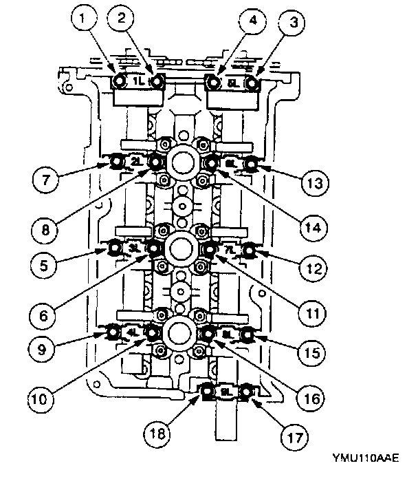
2. Remove the camshaft cap bolts in the order indicated in the figure in several passes.
TIMING CHAIN ASSEMBLY
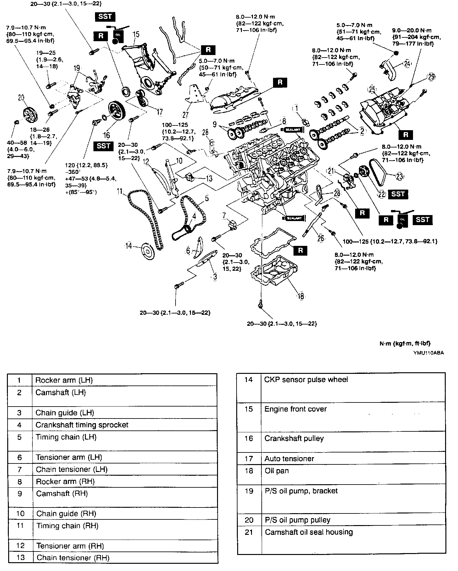
1. Assemble in the order indicated in the table.
Camshaft (LH) Assembly Note
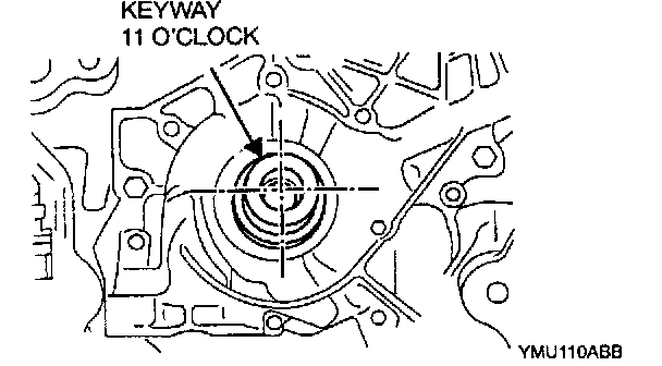
1. Turn the crankshaft clockwise to position the crankshaft keyway in the 11 o'clock position.
2. Install the camshafts (LH).
1. Position the intake camshaft so that the mark is at 9 o'clock direction.
2. Position the exhaust camshaft so that the mark is at 12 o'clock direction.
Caution: Do not install thrust caps 1L and 5L at this time, or damage to the thrust caps may occur.
Note
- Tighten the camshafts caps at specified torque after assembling the timing chain.
- The camshaft bearing caps are numbered to make sure they are assembled in their original positions.
3. Hand tighten the camshaft (LH) caps in their original positions.
Timing Chain (LH) Assembly Note
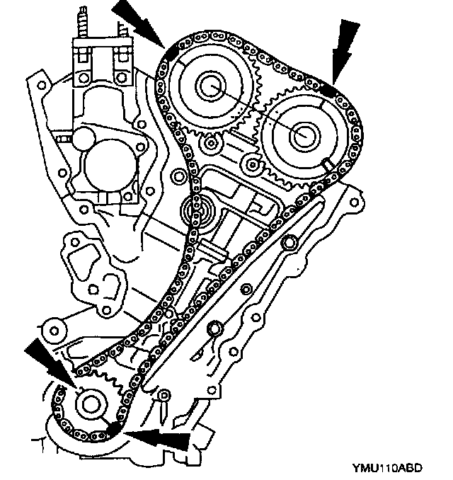
1. Install the timing chain (LH) by aligning the colored links on the timing chain (LH) with the marks on the timing sprockets.
Caution: Install the camshaft bearing thrust caps after installing the other bearing caps, or damage to the thrust caps may occur.
2. Align the camshaft end play using the camshaft bearing thrust caps 1L and 5L, and tighten the other bearing caps.
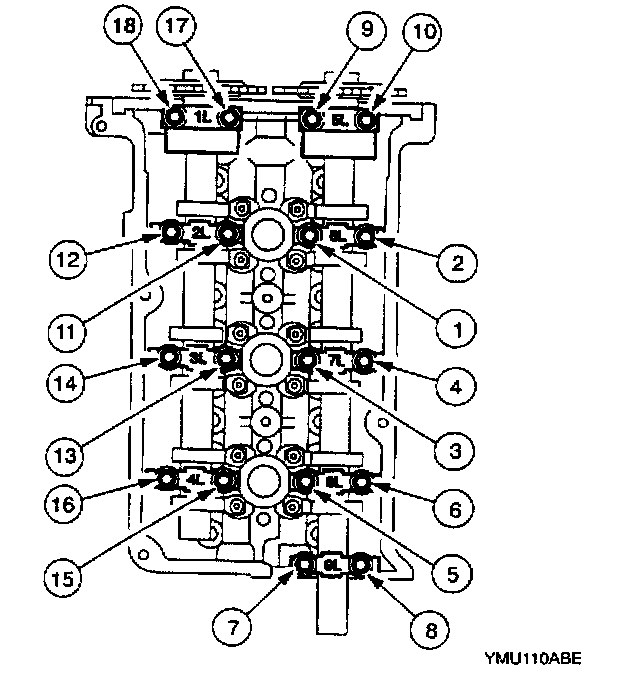
3. Tighten the bearing caps in the order indicated in the figure in several passes.
Camshaft (RH) Assembly Note
1. Turn the crankshaft clockwise to position the crankshaft keyway in the 3 o'clock position.
2. Install the camshafts (RH).
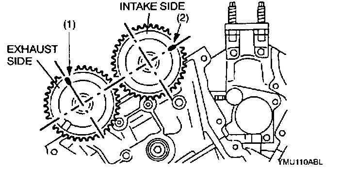
1. Position the exhaust camshaft so that the mark is at 12 o'clock direction.
2. Position the intake camshaft so that the mark is at 3 o'clock direction.
Caution: Do not install thrust caps 5R and 1R at this time, or damage to the thrust caps may occur.
Note
- Tighten the camshafts caps at specified torque after assembling the timing chain.
- The camshaft bearing caps are numbered to make sure they are assembled in their original positions.
3. Hand tighten the camshaft caps (RH) in their original positions.
Timing Chain (RH) Assembly Note
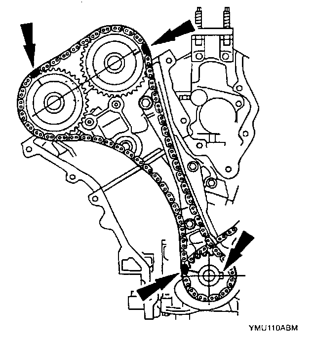
1. Install the timing chain (RH) by aligning the colored links on the timing chain (RH) with the marks on the timing sprockets.
Caution: Install the camshaft bearing thrust caps after installing the other bearing caps, or damage to the thrust caps may occur.
2. Align the camshaft end play using the camshaft bearing thrust caps 1R and 5R, and tighten the other bearing caps.
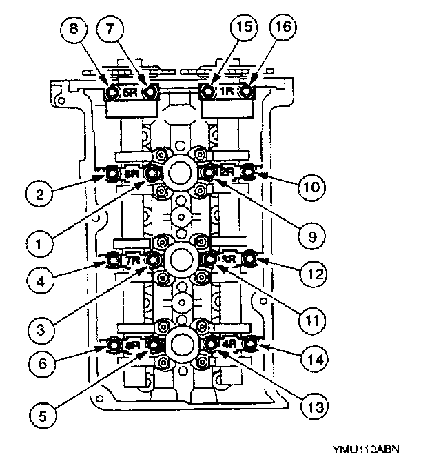
3. Tighten the bearing caps in the order indicated in the figure in several passes.
4. Install the chain tensioner and remove the retaining wire.
5. Turn the crankshaft clockwise 1 and 2/3 turns to position the crankshaft keyway in the 11 o'clock position.
6. Verify that RFF marks on the camshaft sprockets are aligned.
Crankshaft Position (CKP) Sensor Pulse Wheel Assembly Note
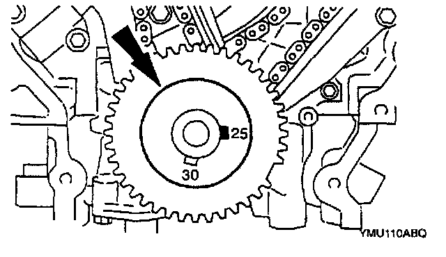
1. Using the keyway marked 25L (blue paint stripe), install the rotor with the indentation towards the front.
Engine Front Cover Assembly Note
1. Apply a 6 mm (0.24 inch) dot of silicon sealant as indicated in the figure (mating faces).
2. Tighten the bolts and studs in the order indicated in the figure.
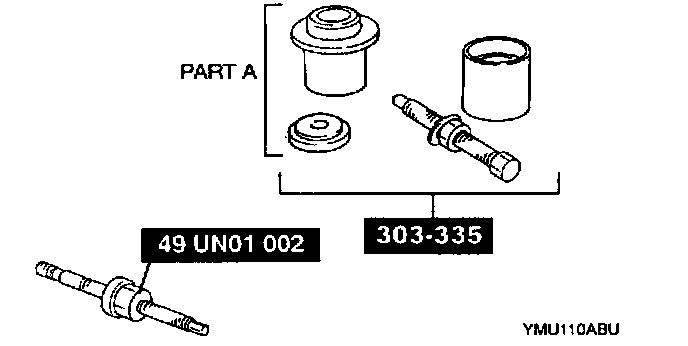
3. Assemble the front oil seal using part A of the SST (49 UN30 3335) and the SST (49 UN01 002) in the following order.
1. Apply clean engine oil to the oil seal.
2. Push the oil seal slightly in by hand.
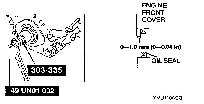
3. Compress the oil seal using the SSTs.
Crankshaft Pulley Assembly Note
1. Using the silicone sealant, seal the keyway in the crankshaft pulley.
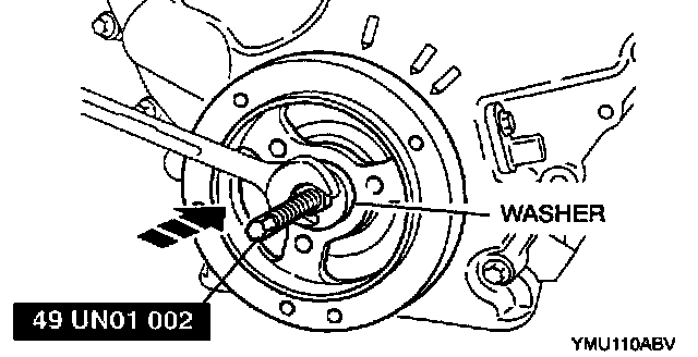
2. Install the crankshaft pulley using the SST and washer of crankshaft pulley lock bolt washer.
3. Hold the crankshaft using the SST
4. Tighten the crankshaft pulley lock bolt in four steps.
1. Tighten to 120 Nm (12.2 kgf-m, 88.5 ft. lbs.).
2. Loosen 360° (one full turn) in reverse order.
3. Tighten 47 - 53 Nm (4.8 - 5.4 kgf-m, 35 - 39 ft. lbs.).
4. Tighten 85° - 95°.
Oil Pan Assembly Note
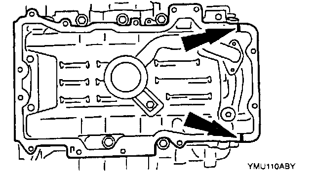
1. Apply silicone sealant to the mating faces as indicated in the figure.
Dot diameter: 10 mm (0.39 Inch)
2. Install the oil pan with a new gasket.
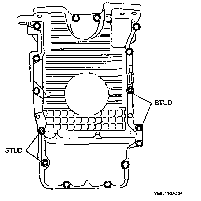
3. Install the bolts and studs as indicated in the figure.
4. Align the cylinder block and the rear face of the oil pan using the straight edge.
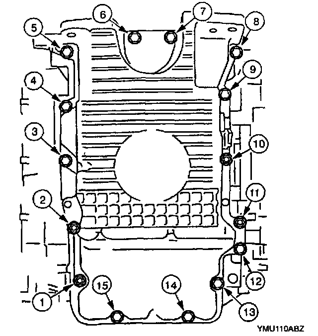
5. Tighten the bolts and studs in the order indicated in the figure.
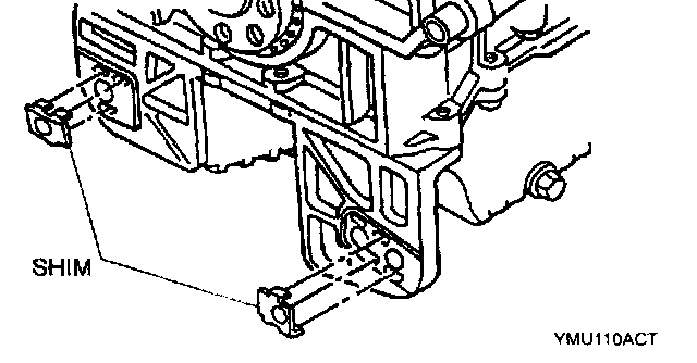
6. Measure the height between the cylinder block and the oil pan.
- If the clearance is 0 -0.25 mm (0 -0.009 inch), oil pan assembly is completed.
- If the clearance is -0.26 -0.550 mm (-0.010 -0.019 in), install the 0.25 mm (0.0098 inch) shim (silver) to the oil pan.
- If the clearance is -0.551 -0.575 mm (-0.020 -0.030 inch), install the 0.550 mm (0.0020 inch) shim (gold) to the oil pan.
- If the clearance is more than -0.575 mm (-0.030 inch), or the oil pan is higher than the cylinder block, reinstall the oil pan.
P/S Oil Pump, Bracket Assembly Note
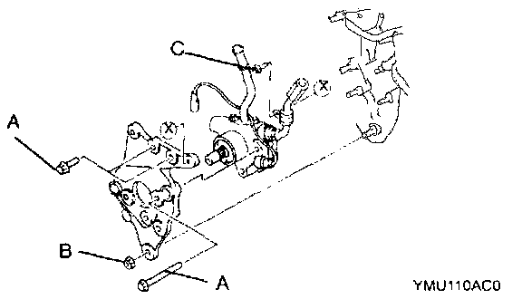
1. Tighten the bolts and nuts.
Tightening torque
A: 19 - 25 Nm (1.9 - 2.6 kgf-m, 14 - 18 ft. lbs.)
B: 7.9 - 10.7 Nm (80 - 110 kgf-cm, 69.5 - 95.4 inch lbs.)
C: 7.9 - 10.7 Nm (80 - 110 kgf-cm, 69.5 - 95.4 inch lbs.)
Camshaft Oil Seal Housing Assembly Note
1. Apply clean engine oil to the oil seal.
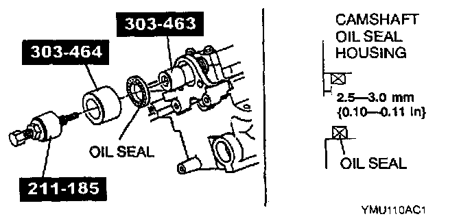
2. Install the camshaft oil seal using the SSTs.
Water Pump Drive Pulley Assembly Note
1. Install the water pump pulley using the SST
Cylinder Head Cover Assembly Note
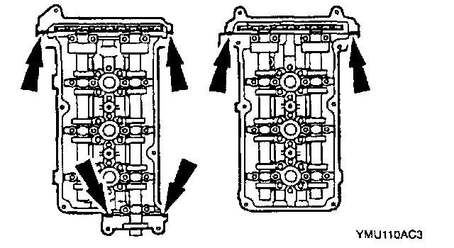
1. Apply silicone sealant to the mating faces as indicated in the figure.
2. Install the cylinder head cover with a new gasket.
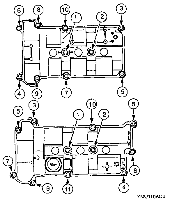
3. Tighten the bolts in the order indicated in the figure.