Variable Induction Control Solenoid: Testing and Inspection
VARIABLE TUMBLE CONTROL SYSTEM (VTCS) SOLENOID VALVE INSPECTION [ZM]Simulation Test
1. Carry out the "VTCS Operation Inspection". Refer to Powertrain Management.
- If not as specified, perform the further inspection for the VTCS solenoid valve.
Airflow Inspection
Note: Perform the following test only as directed.
1. Remove the VTCS solenoid valve.
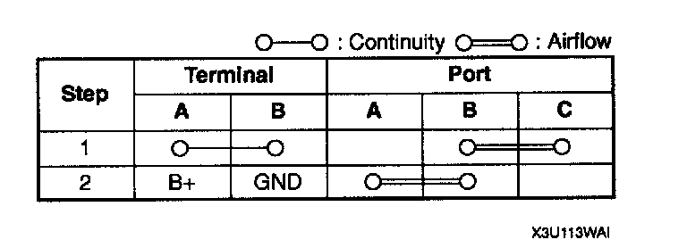
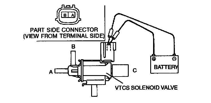
2. Inspect for the air flow inspection each port under the following condition.
- If as specified, replace the VTCS solenoid valve.
- If as specified but the "VTCS Operation Inspection" is failed, inspect evaporative hoses for improper routing, kinks or leakage, and inspect "Circuit Open/Short Inspection".
- If there is an open or short circuit, repair or replace wiring harnesses.
- If the above open or short circuit is okay, replace VTCS solenoid valve.
Circuit Open/Short Inspection
1. Remove the PCM.
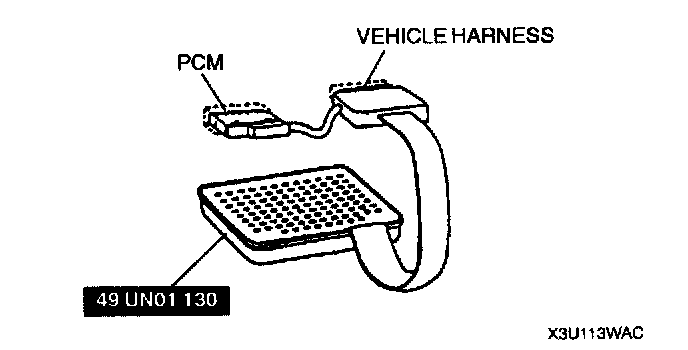
2. Connect the SST (104 Pin Breakout Box) to the PCM as shown.
3. Tighten the connector attaching screw.
Tightening torque: 7.9 - 10.7 Nm (80 - 110 kgf-cm, 69.5 - 95.4 inch lbs.)
4. Inspect for an open or short circuit in the following wiring harnesses by probing the applicable sensor and SST (104 Pin Breakout Box) terminals with ohmmeter leads.
Open circuit
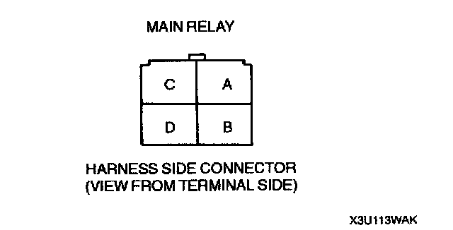
- Power circuit (VTCS solenoid valve connector terminal A and main relay connector terminal D through common connector)
- GND circuit (VTCS solenoid valve connector terminal B and PCM connector terminal 19)
Short circuit
- VTCS solenoid valve connector terminal A and main relay connector terminal D through common connector to GND
5. Reconnect the VTCS solenoid valve connector.
6. Reconnect the negative battery cable.