Clutch: Service and Repair
CLUTCH UNIT REMOVAL/INSTALLATION
1. Remove in the order indicated in the table.
2. Install in the reverse order of removal.
Clutch Cover Removal Note
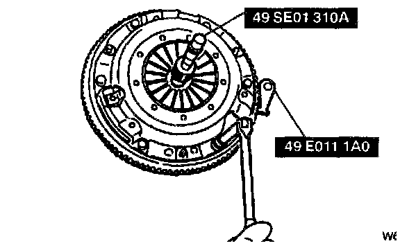
1. Install the SST.
2. Loosen each bolt one turn at a time in a crisscross pattern until spring tension is released.
3. Remove the clutch cover and disc.
Pilot Bearing Removal Note
Note: The pilot bearing does not need to be removed unless you are replacing it.
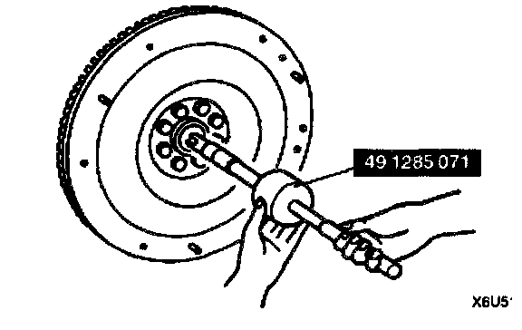
1. Use the SST to remove the pilot bearing.
Flywheel Removal Note
1. Hold the flywheel using the SST.
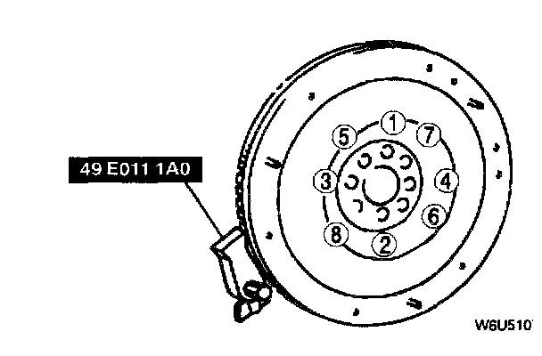
2. Remove the bolts evenly and gradually in a crisscross pattern.
Note:
- FS: 6 bolt
- KL: 8 bolt
3. Remove the flywheel.
Flywheel Installation Note
1. Install the flywheel to the crankshaft.
2. When reusing the bolts, clean and apply sealant to the threads. (FS)
Note: No sealant is needed when using new bolts. (FS)
3. Hand-tighten the flywheel lock bolts.
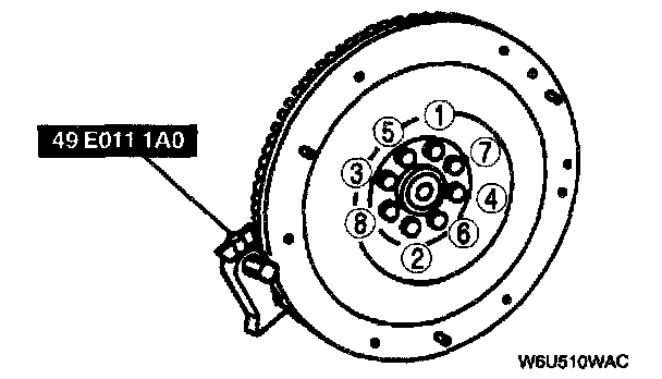
4. Install the SST to the flywheel.
5. Gradually tighten the flywheel lock bolts in a crisscross pattern.
Tightening torque
FS: 97 - 102 Nm (9.9 - 10.5 kgf-m, 71 - 75 ft. lbs.)
KL: 61 - 67 Nm (6.2 - 6.9 kgf-m, 45 - 49 ft. lbs.)
Note:
- FS: 6 bolt
- KL: 8 bolt
Pilot Bearing Installation Note
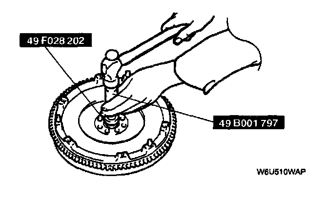
1. Install a new pilot bearing using a SST.
Bearing installation depth 0.0 - 0.4 mm (0.0 - 0.015 inch)
Clutch Disc Installation Note
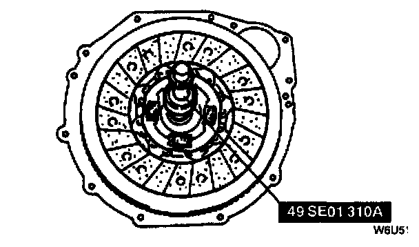
1. Hold the clutch disc position using the SST.
Clutch Cover Installation Note
1. Install the SSTs.
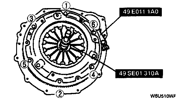
2. Tighten the bolts evenly and gradually in a crisscross pattern.
Tightening torque 18 - 26 Nm (1.8 - 2.7 kgf-m, 14 - 19 ft. lbs.)
CLUTCH COVER INSPECTION
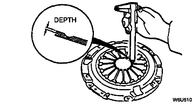
1. Measure the wear of the diaphragm spring fingers.
Depth 0.6 mm (0.0236 inch) max.
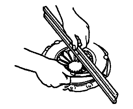
2. Measure the flatness of the pressure plate using a straight edge and a feeler gauge.
- Replace the clutch cover if not as specified.
Maximum clearance 0.5 mm (0.020 inch)
3. When checking the diaphragm spring fingers, mount a dial indicator on the cylinder block.
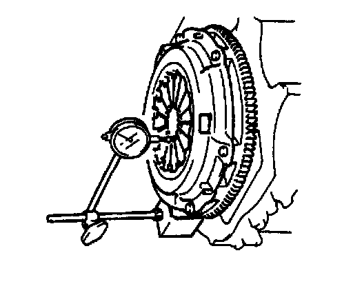
4. Rotate the flywheel and check for misaligned diaphragm spring fingers.
- Replace the clutch cover if not as specified.
Misalignment 0.6 mm (0.0236 inch) max.
CLUTCH DISC INSPECTION
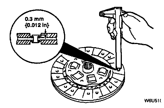
1. Using vernier calipers, measure the thickness of the lining at a rivet head on both sides.
- Replace the clutch disc if its thickness is less than the minimum.
Thickness 0.3 mm (0.012 inch) min.
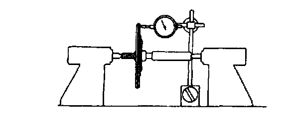
2. Measure the clutch disc runout using a dial indicator.
- Replace the clutch disc if runout is excessive.
Runout 0.7 mm (0.0276 inch) max.
CLUTCH RELEASE COLLAR INSPECTION
Caution: Cleaning the clutch release collar with cleaning fluids or a steam cleaner can wash the grease out of the sealed bearing.
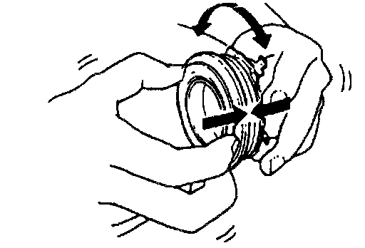
1. Turn the collar while applying force in the axial direction.
- If the collar sticks or has excessive resistance, replace it.
PILOT BEARING INSPECTION
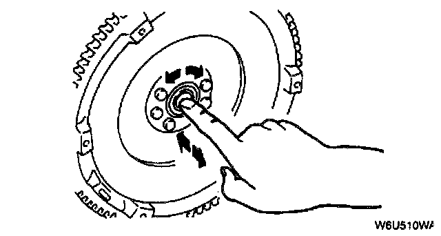
1. Without removing the pilot bearing from the flywheel, turn the bearing while applying force in the axial direction.
- If the bearing sticks or has excessive resistance, replace it.
FLYWHEEL INSPECTION
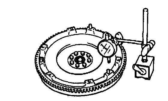
1. Install a dial gauge on the cylinder block.
2. Measure the flywheel runout using a dial indicator.
- Replace the flywheel if runout is excessive.
Runout 0.2 mm (0.008 inch) max.