Shift Solenoid: Testing and Inspection
SOLENOID VALVES INSPECTION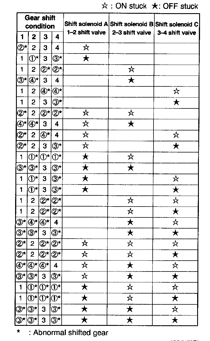
Gear Shift Pattern Under Solenoid Valve Failure
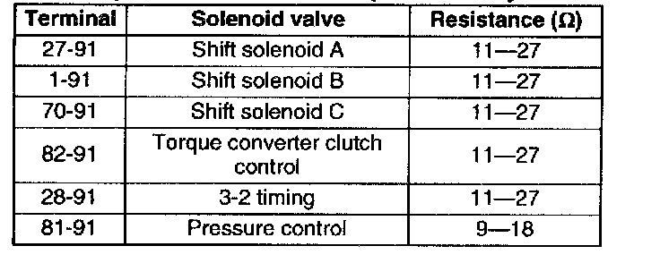
Resistance Inspection (on-vehicle)
1. Disconnect the negative battery cable.
2. Connect the SST (104-pin Breakout Box) to the PCM harness with PCM disconnected.
3. Measure the resistance between the following terminals of the SST.
- If not as specified, inspect the ground, then perform resistance inspection (off-vehicle).
ATF temperature: -40 - 160°C (-40 - 320°F)
4. Connect the negative battery cable.
Resistance Inspection (off-vehicle)
1. Remove the control valve body.
2. Remove the solenoid valve(s).
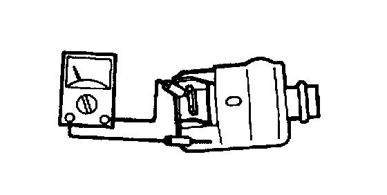
3. Measure the resistance of each solenoid valve individually.
- If not as specified, replace the solenoid valve.
- If the solenoid valve okay, inspect the wiring harness. (Solenoid valve-Coupler component)
Resistance
Shift solenoid A, B. C, TCC control solenoid valve, and 3-2 timing solenoid valve: 11 - 27 Ohms
Resistance
Pressure control solenoid: 9 - 18 Ohms
4. Install the solenoid valve(s).
5. Install the control valve body.
Simulation Test
1. Connect the SST (NGS tester) to the DLC-2.
2. Turn the ignition key to ON. (Engine OFF)
3. Select the SIMULATION TEST function on the NGS display.
4. Select the SIMULATION TEST mode.
5. Highlight 3-2 time PID and press TRIGGER.
6. Press START.
7. Press TRIGGER to send ON signal to the solenoid valve.
8. Verify that each control valve operates with a "click".
- If the "click" is not heard, replace the solenoid valve.
9. Perform simulation test for the remaining solenoid valves (PIDs) in the same manner.
- LINE
- SHIFT A
- SHIFT B
- SHIFT C
- TCC CON
Inspection of Output Duty
Pressure control solenoid
1. Connect the (+) terminal of a dwell meter to terminal 81 at the PCM and the (-) terminal to a ground. Set the dwell meter selector to the 4 cylinder position.
2. Apply parking brake and use wheel chocks at the front and rear of the wheels.
3. Start the engine.
4. Depress the brake pedal firmly.
5. Shift the selector lever to D range.
Caution:
- If the accelerator pedal is depressed for longer then 5 seconds while the brake pedal is depressed, the transaxle could be damaged. Therefore, do Step 6 within 5 second of each other.
Note:
- The dwell meter indicates the OFF duty ratio.
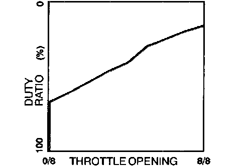
6. Depress the accelerator pedal slowly and verify that the duty ratio charges as shown in the graph.
- If not as specified, inspect the pressure control solenoid.