Electronic Control System
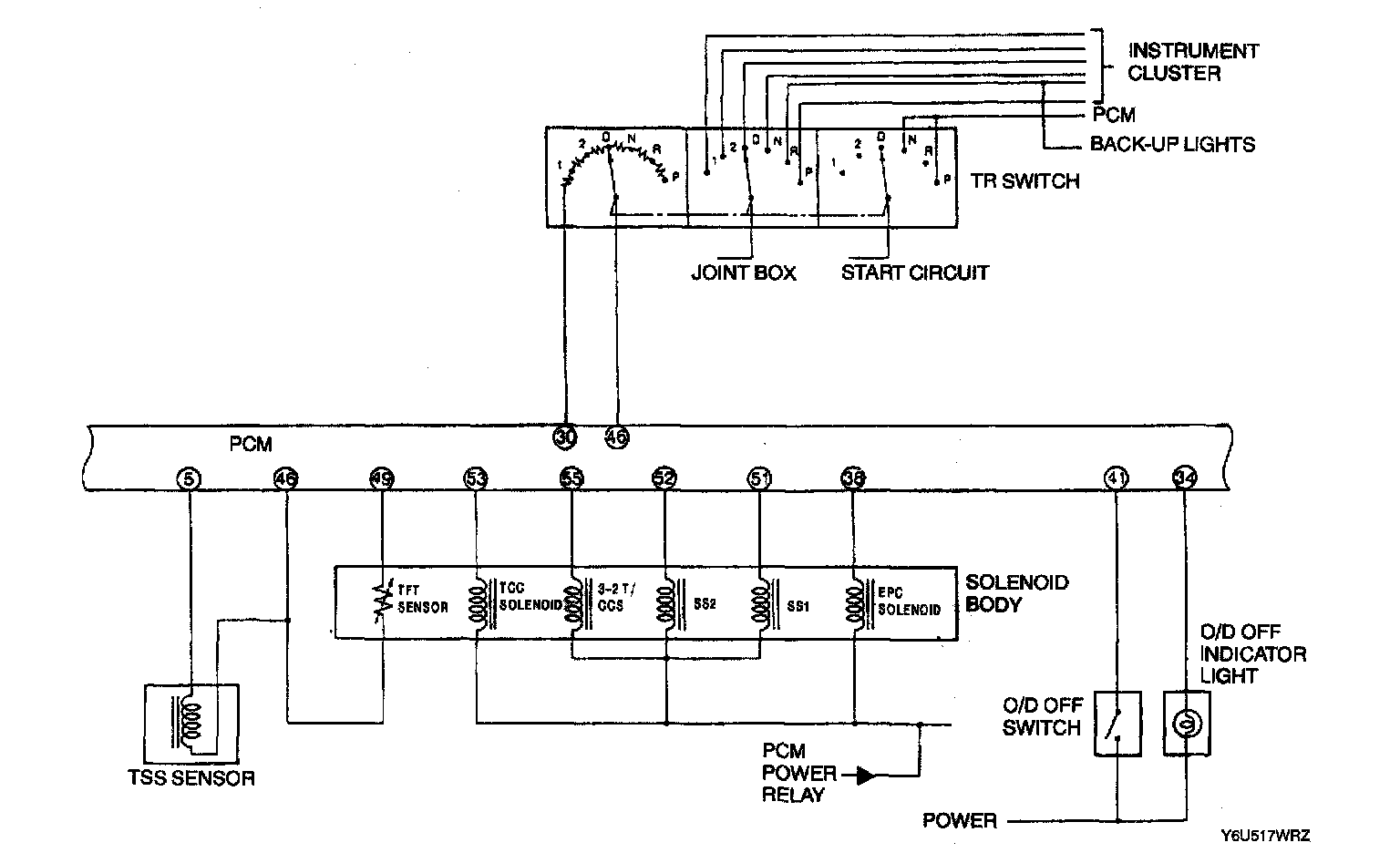
System Wiring Diagram
Transaxle Fluid Temperature (TFT) Sensor Description
Description
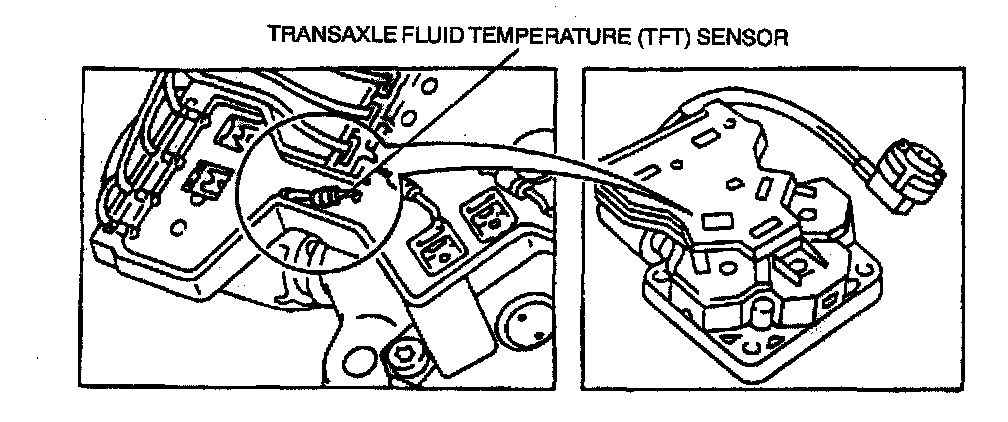
- The TFT sensor is located on the transaxle solenoid body. It is a temperature-sensitive device called a thermistor. The resistance value of the TFT sensor will vary with temperature change.
- The PCM monitors the voltage across the TFT sensor to determine the temperature of the ATF.
Function
- The PCM uses this signal to determine shift scheduling and control pressure for cold temperatures operation. The PCM also inhibits torque converter clutch operation at low transaxle temperatures and adjusts EPC pressures for temperature.
Symptoms (DTCs:P0712, P0713, P1711, P1713 and/or P1718)
- Improper torque converter clutch operation and EPC pressure control.
Transmission Range (TR) Sensor
Description
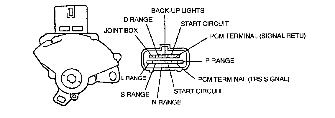
- The PCM sends a voltage signal to the TR sensor. The TR sensor incorporates a series of step down resistors which act as a voltage divider. The PCM monitors this voltage which corresponds to the position of the selector lever (P,R,N,D,2,1).
- The TR sensor is located on the top of the transaxle. The TR sensor also contains the neutral/start and backup light circuits.
- This sensor also contains contacts for the near position display in the instrument cluster.
Function
- Determines desired gear and line pressure.
Symptoms (DTCs: P0707, P0708 and/or P1705)
- Harsh engagements and firm shift feel. Engine may not crank. May downshift to a lower gear. 2GR or 3GR operation. Transaxle not indicating the proper gear. No 4GR operation. No 1 GR (1 range). 3GR in 1 range. Illuminate MIL (except P1705).
Stoplight Switch
Description
- The stoplight switch inputs a voltage signal to the PCM when the brakes are applied. The switch is closed when the brakes are applied and open when they are released.
Function
- Disengages the torque converter clutch when brake is applied.
Symptoms (DTC:P1703)
Failed "ON"
^ The torque converter clutch will not engage at less the 1/3 throttle.
Failed "OFF" or not connected
^ The torque converter clutch will not disengage when brake is applied.
O/D OFF Switch
Description
- The O/D OFF switch is a momentary contact switch. When the O/D OFF switch is pressed, a signal is sent to the PCM.
Function
- The PCM then energizes the O/D OFF indicator lamp and engages or disengages 4GR operation and provides coast braking in 2GR and 3GR.
Symptoms (DTC:P1783 during KOER)
Failed "ON"
^ Vehicle will not upshift/downshift automatically, coasting clutch engages in 2GR and 3GR.
Failed "OFF"
^ No modification to the shift pattern.
Turbine Shaft Speed (TSS) Sensor
Description
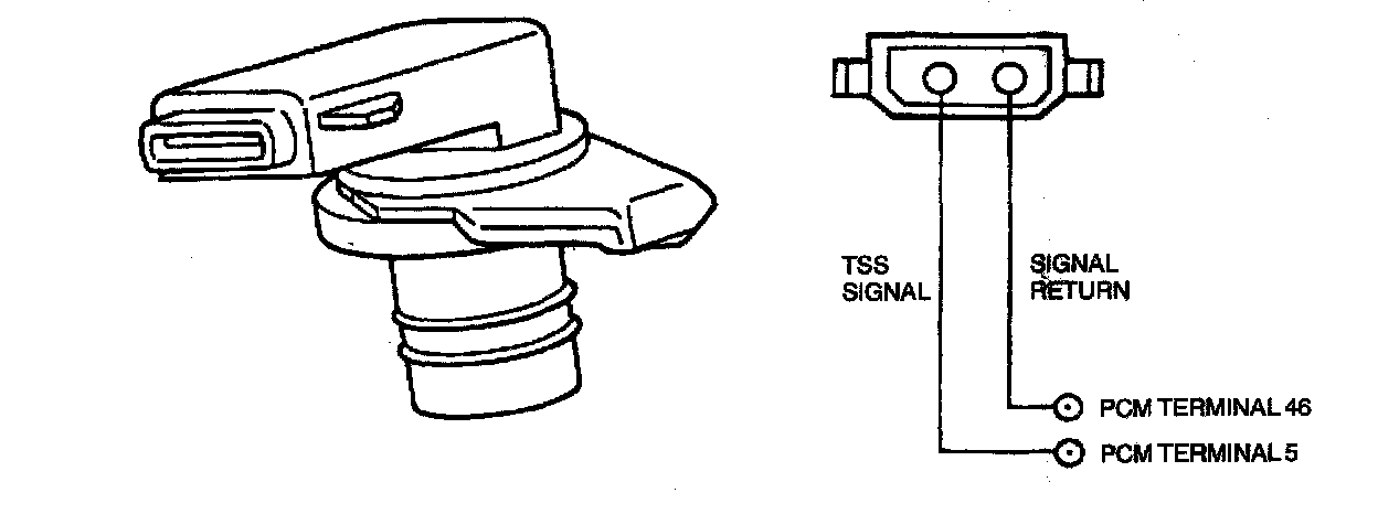
- A TSS is a magnetic pickup that sends a signal to the PCM that indicates transaxle turbine shaft input speed.
Function
- Provides converter turbine speed information for torque converter clutch control strategy. Also used in determining static EPC pressure setting during shifts.
Symptoms (DTC:P0715)
- No torque converter clutch engagements, harsh shifts. No fourth gear operation.
- Engine braking in 2GR and 3GR. Illuminate MIL.
Vehicle Speedometer Sensor (VSS)
Description
- The VSS is a magnetic pickup that sends a signal to the PCM. This VSS signal tells the PCM the vehicle speed.
Function
- Used to determine shift scheduling and EPC pressure control.
Symptoms (DTCs:P0500, P0503 and/or P1501)
- Firm shirt feel, abnormal schedules, unexpected downshifts may occur at close throttle.
- No 4GR operation. Engine parking in 2nd and 3rd gear. No torque converter clutch application.
- Illuminate MIL (P0500) and flush O/D OFF indicator (P0503).
Engine Coolant Temperature (ECT) Sensor
Description
- The ECT sensor detects the temperature of the engine coolant and supplies the information to the PCM.
Function
- ECT is used to control torque converter clutch operation. (HOT operation)
Symptoms
- Torque converter clutch will always be "OFF", resulting in reduced fuel economy.
Mass Air Flow (MAF) Sensor
Description
- The sensor directly measures the mass of the air flowing into the engine.
- The sensor output is a D.C. (analog) signal ranging from about 0.5 volts to 50 volts used by the PCM to calculate the injector pulse width.
- For transaxle strategies, this sensor is used for EPC pressure control, shift and torque converter clutch scheduling.
Function
- Line pressure control, shift and torque converter clutch scheduling.
Symptoms
- Incorrect shift schedule, line pressure high or low, incorrect torque converter clutch engagement scheduling and symptoms similar to a TP sensor malfunction.
Throttle Position (TP) Sensor Description
Description
- The TP sensor is a potentiometer mounted on the throttle body. The TP sensor detects the position of the throttle plate and sends this information to the PCM as a varying voltage signal.
- If a malfunction occurs in the TP circuit, the PCM will recognize that the TP sensor signal is out of specification. The PCM operates at high pressure transaxle damage.
Function
- Shift scheduling, EPC pressure control and torque converter clutch control.
Symptoms
- Harsh engagements, firm shift feel, abnormal shift schedule, torque converter clutch does not engage, torque converter clutch cycling. Flash Malfunction Indicator Light (MIL).
Magnetic Clutch Description
Function
- The PCM adjusts EPC pressure when A/C compressor clutch is engaged to compensate for the additional load on the engine.
Symptoms
Failed "ON"
^ Line pressure slightly low with A/C off.
Failed "OFF"
^ Line pressure slightly high with A/C off.
Solenoid Body
Description

- The PCM controls the operation of the transaxle through wiring to the solenoid body mounted on the control valve body.
- The solenoid body contains the:
- Transaxle Fluid Temperature (TFT) Sensor. Electronic Pressure Control (EPC) Solenoid.
- Shift Solenoid No. 1 (SST )
- Shift Solenoid No.2 (SS2)
- Torque Converter Clutch (TCC) Solenoid
- 3-2 Timing/Coasting Clutch Solenoid (3-2T/CCS)
Electronic Pressure Control (EPC) Solenoid
Description
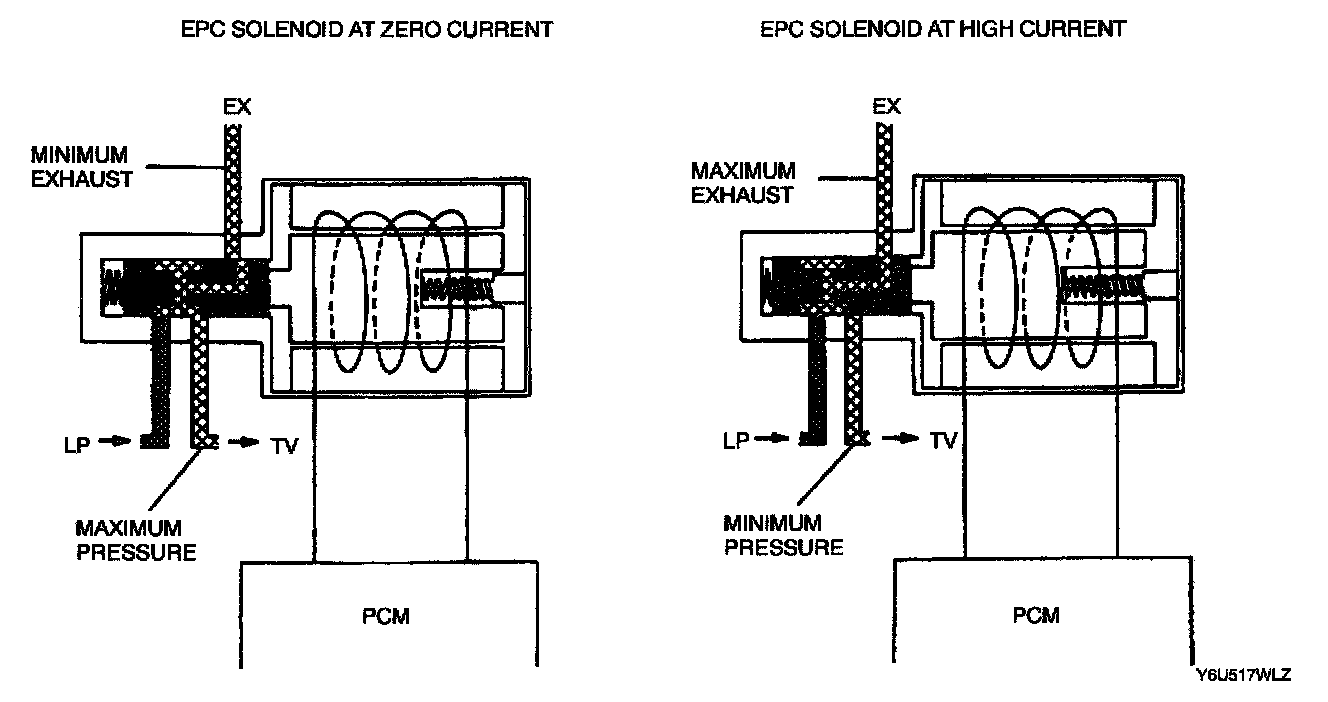
- The EPC solenoid is a variable force style solenoid. This type solenoid is an electro-hydraulic actuator combining a solenoid and a regulating valve.
- EPC solenoid regulates line pressure. This is controlled by producing a resisting pressure to the main regulator circuit. The LP pressure controls clutch application pressures.
Function
- Regulates line pressure.
Symptoms (DTCs:P1746 and/or P1747)
- Flash O/D OFF indicator (P1746) and illuminate MIL (P1747). Failed "ON"
- Minimum EPC pressure (minimum trans-torque capacity).
- May flash O/D OFF indicator. Failed "OFF"
- Maximum EPC pressure, harsh engagements and harsh shifts.
Shift Solenoids No.1 and No.2 (SS1,SS2)
Description
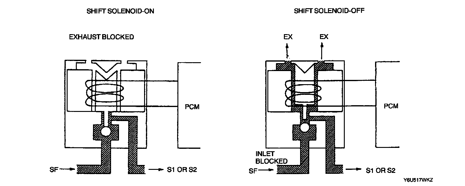
- SS1 and SS2 provide gear selection of first through fourth gears by providing ON/OFF pressure control to the shift valves.
Function
- Gear selection
Symptoms (DTCs: P0731, P0732, P0733, P0734, P0750, P0751, P0755 and/or P0756)
- Improper gear selection depending on failure mode and manual lever position. Refer to shift solenoid failure modes.
- Flash O/D OFF indicator (P0731, P0732, P0733, P0734) and illuminate MIL (P0751, P0755, P0756)
Shift solenoid failure modes
Shift solenoid failure "ALWAYS ON"
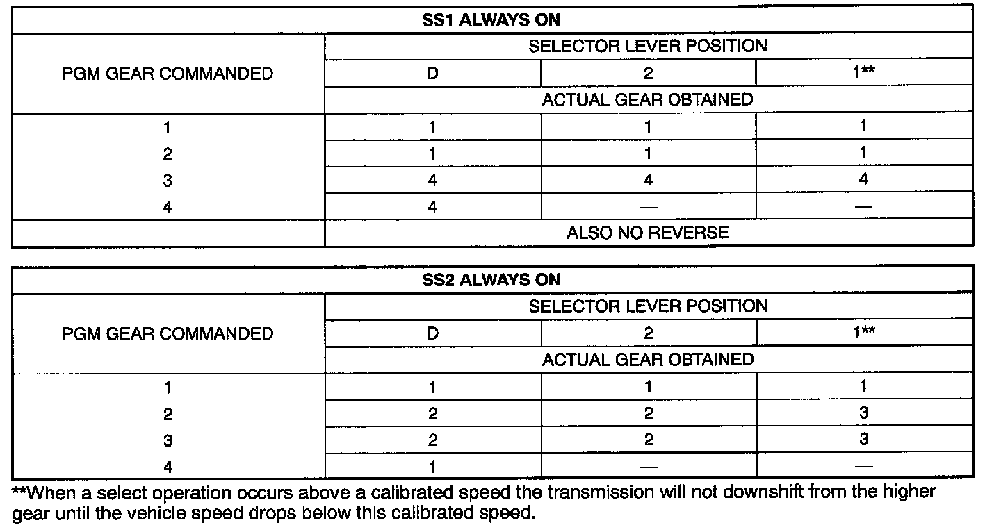
- Failed ON due to PCM and/or vehicle wiring problems, and/or solenoid electrically stuck in the on position, and/or hydraulically or mechanically stuck in the on position.
Shift failure "ALWAYS OFF"
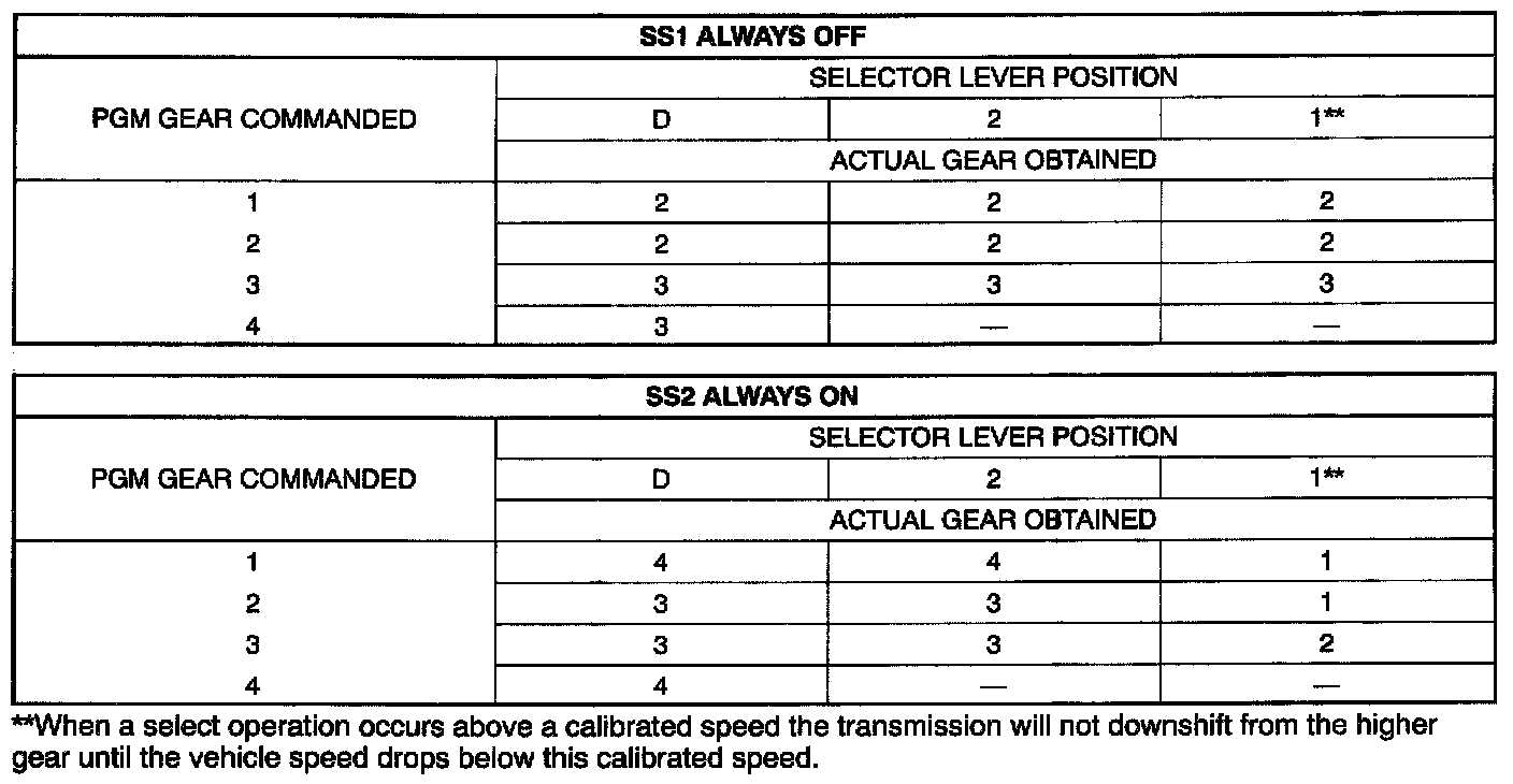
- Failed OFF due to PCM and/or vehicle wiring concerns, and/or solenoid electrically stuck in the off position, and/or hydraulically or mechanically stuck in the off position.
3-2 Timing/Coasting Clutch Solenoid (-2T/CCS)
Description
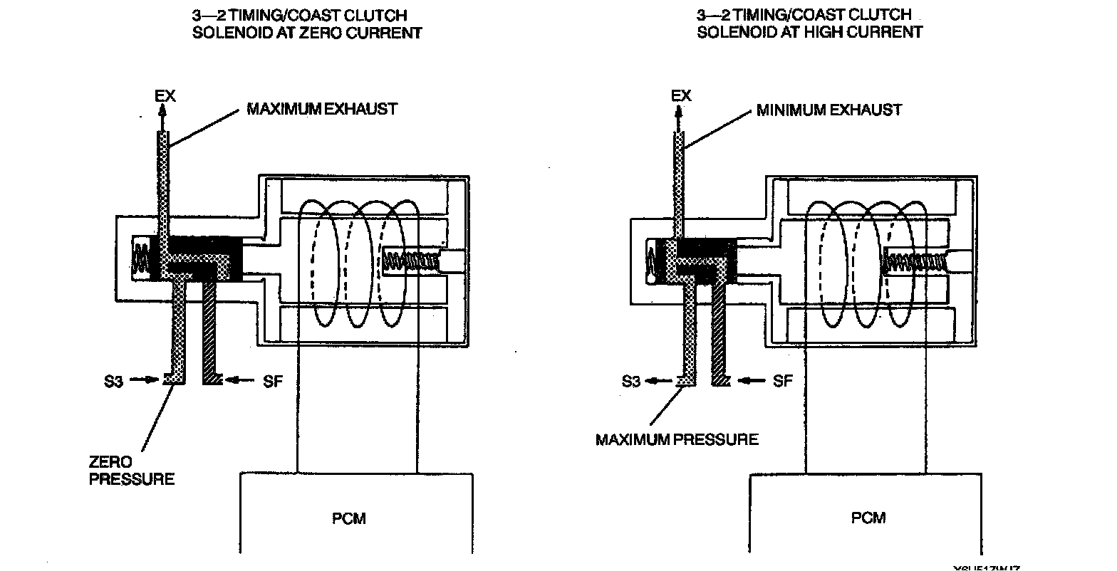
- The 3-2T/CCS is a variable force solenoid. This type of solenoid is an electro-hydraulic actuator combining a solenoid and a regulating valve.
- It supplies pressure to the S3 circuit to control the release of the direct clutch during a 3-2 downshift. This solenoid also regulates the pressure in the S3 circuit to control the application and release of the coasting clutch.
Function
- Use to control the application and release of the coasting clutch and the release timing of the direct clutch.
Symptoms (DTCs:P1788 and/or P1789)
- Flash O/D OFF indicator
Failed "ON"
^ No engine braking (except 4GR), extend 3-2 downshifts or 4 2 downshifts with higher than expected engine rpm.
Failed "OFF"
^ Engine braking in 2GR and 3GR, firm or flared 3-2 downshifts. Harsh 4-3 downshifts.
Torque Converter Clutch (TCC) Solenoid
Description
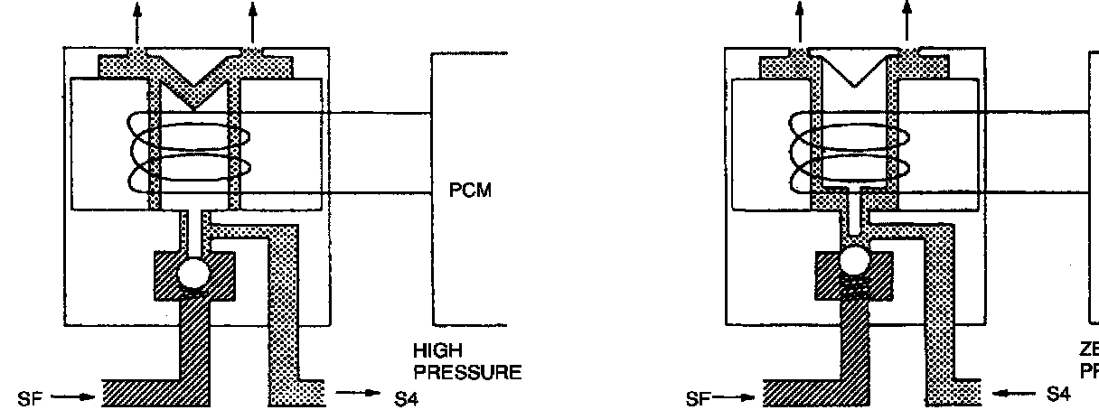
- The TCC solenoid is a pulse width modulating style solenoid. This type solenoid is used to control the engagement and release of the torque converter clutch.
- By modulating the pulse width of the TCC solenoid, the pressure in the S4 circuit varies modulation of the engagement and release of the bypass clutch in the torque converter.
Function
- Used to apply and release the torque converter clutch.
Symptoms (DTCs: P0743, P1742, P1743 and/or P1744)
- Illuminate MIL (P0743, P1742, P1744) and flash O/D OFF indicator (P1743).
Failed "ON"
^ Engine stalls in 2GR (2 range). Engine lugging, poor performance at low engine speed, harsh shifts.
Failed "OFF"
^ Poor fuel economy, overheating, torque converter clutch will not engage.
^ Firm shift feel.
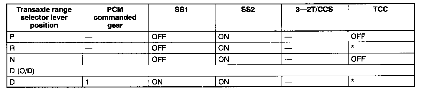
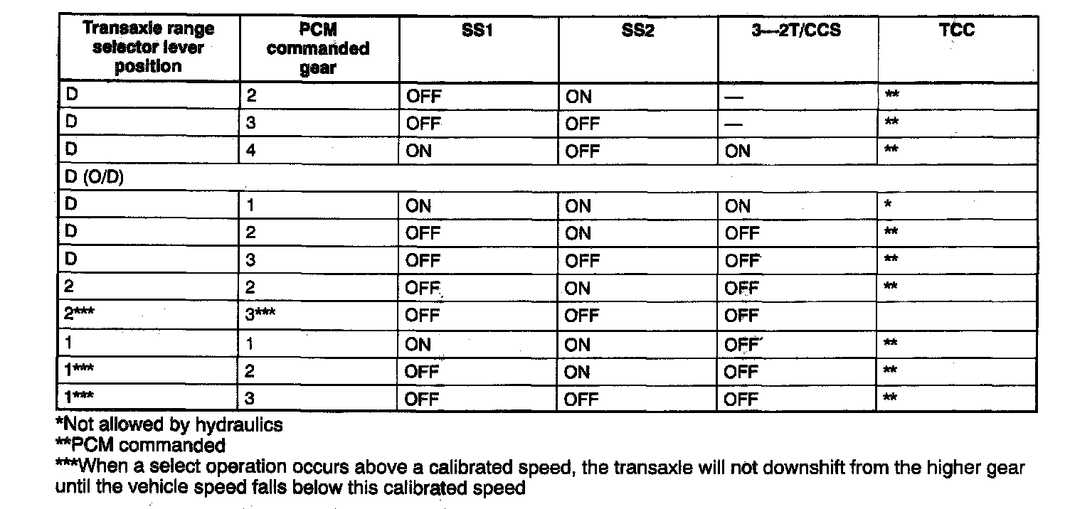
Solenoid valve operation chart
Part 1 of 2
Part 2 of 2
- The solenoid operation chart shows normal solenoid operation for given operation mode.