Fuel Delivery and Air Induction: Service and Repair
FUEL CHARGING WIRING HARNESSRemoval and Installation
WARNING: Do not smoke or carry lighted tobacco or open flame of any type when working on or near any fuel-related components. Highly flammable mixtures are always present and may be ignited. Failure to follow these instructions may result in personal injury.
1. Remove the air cleaner outlet pipe. Refer to AIR CLEANER OUTLET PIPE 2.0L ZETEC.
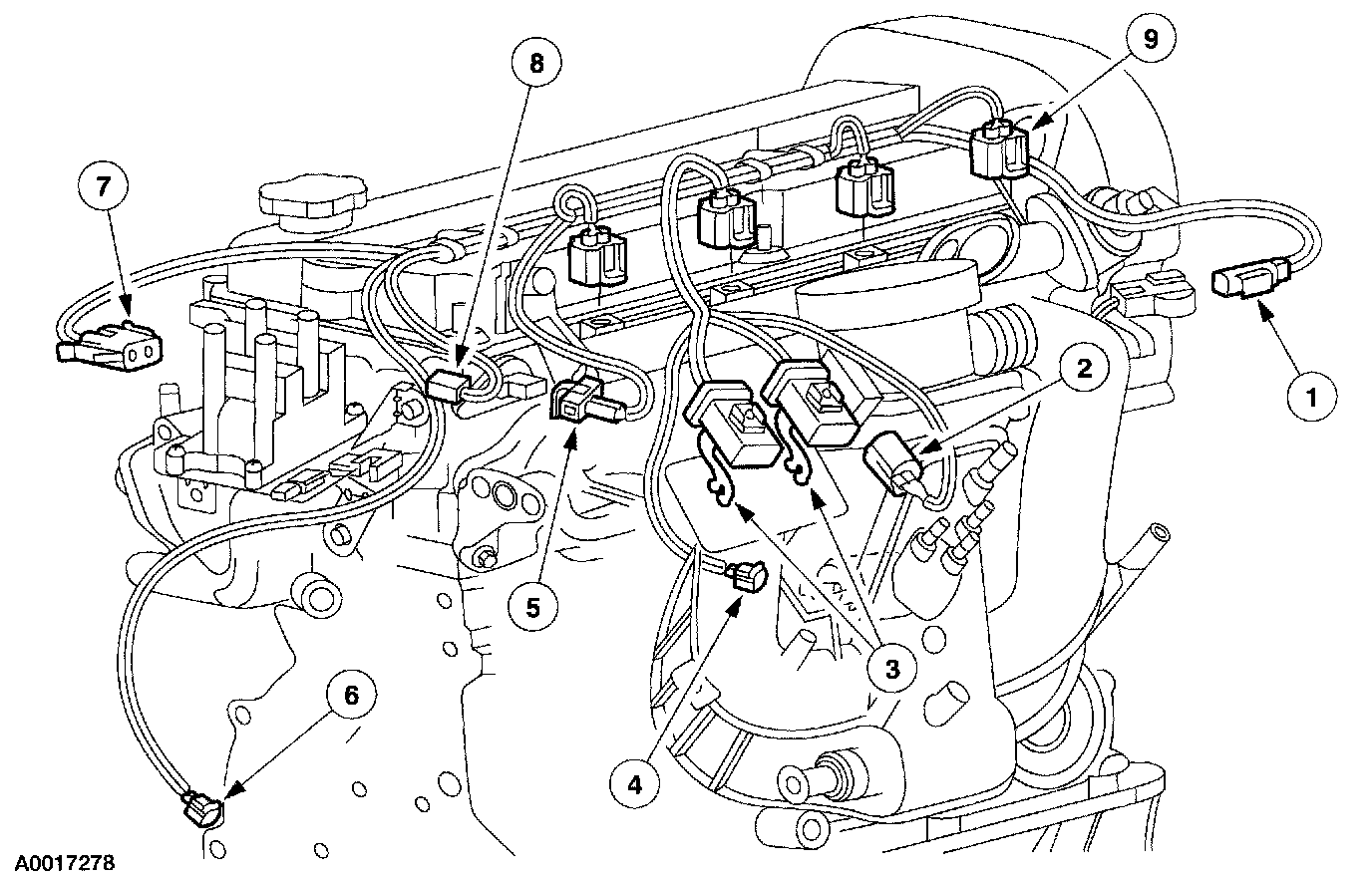
2. Disconnect the following electrical connectors
1. cylinder temperature sensor
2. throttle position sensor
3. wiring harness to vehicle
4. idle air control valve
5. camshaft position sensor
6. crankshaft position sensor
7. ignition coil
8. radio ignition noise suppressor
9. fuel injectors
NOTE: Remove and reinstall new tie straps if necessary.
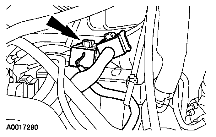
3. Disconnect the wiring harness to vehicle connectors from bracket and remove harness.
4. To install, reverse the removal procedure.
FUEL CHARGING WIRING HARNESS
Removal and Installation
WARNING: Do not smoke or carry lighted tobacco or open flame of any type when working on or near any fuel-related components. Highly flammable mixtures are always present and may be ignited. Failure to follow these instructions may result in personal injury.
1. Remove the upper intake manifold. Refer to UPPER INTAKE MANIFOLD.
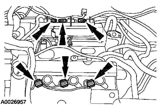
2. Disconnect the coil-on-plug electrical connectors.
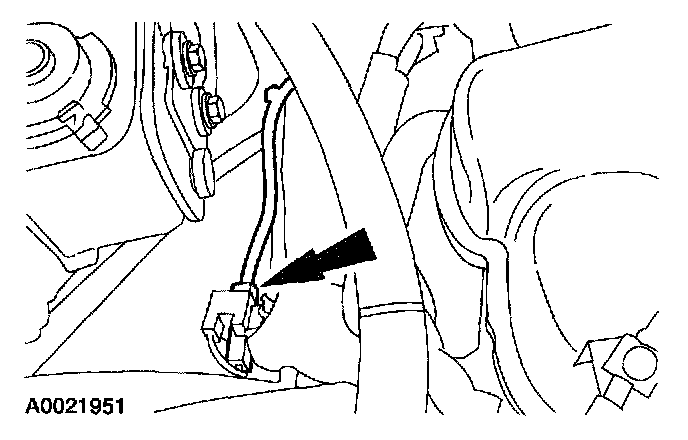
3. Disconnect the radio ignition noise suppressor electrical connector.
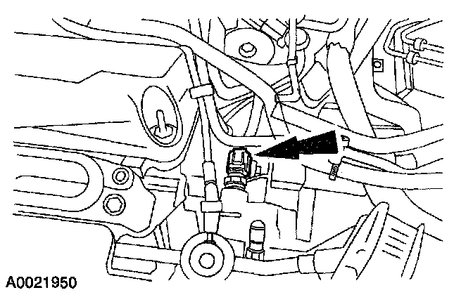
4. Remove the engine coolant temperature (ECT) sensor electrical connector.
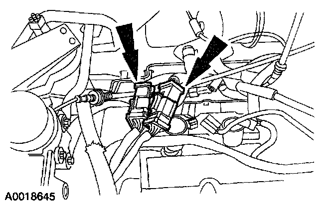
5. Disconnect the 16-pin electrical connectors.
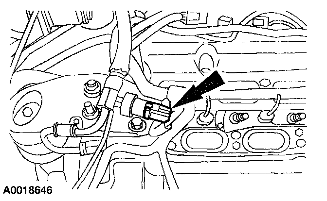
6. Disconnect power steering pressure (PSP) switch electrical connector.
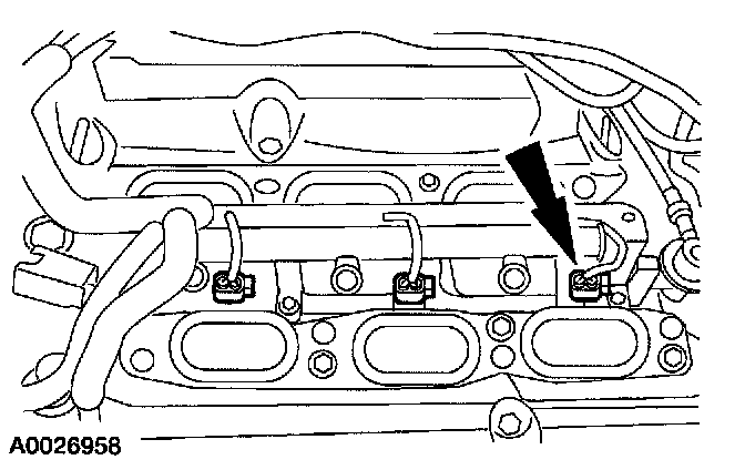
NOTE: One connector is shown, the other five connectors are similar.
7. Disconnect the six fuel injector electrical connectors and release the wiring harness locators from the fuel injection supply manifold.
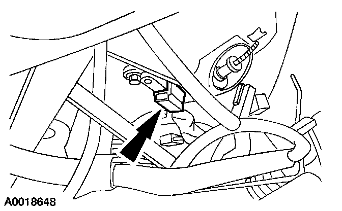
8. Disconnect the camshaft position (CMP) sensor electrical connector.
9. Remove the RH wheel and tire assembly.
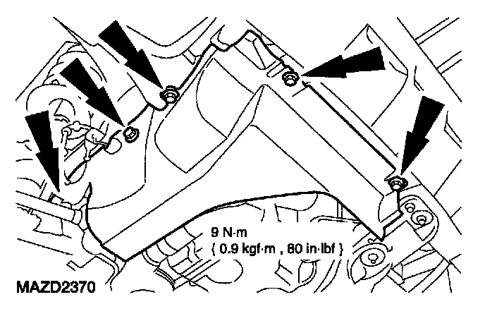
10. Remove the RH lower splash shield.
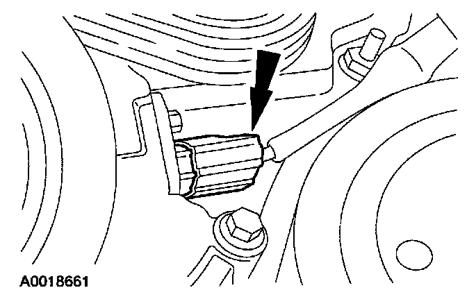
11. Disconnect the crankshaft position (CKP) sensor electrical connector.
NOTE: The oil pressure sensor is located behind the rear of the A/C compressor. The A/C compressor has been removed for clarity.
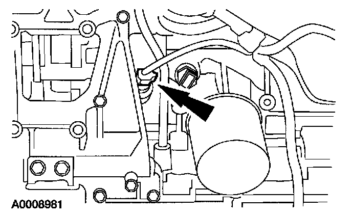
12. Disconnect the oil pressure sensor electrical connector.
13. Lower the vehicle.
14. Remove the fuel charging wiring harness from the vehicle.
15. To install, reverse the removal procedure.