Rear Cross-Member: Service and Repair
REAR CROSSMEMBER REMOVAL/INSTALLATIONCaution:
^ Performing the following procedures without first removing the ABS wheel-speed sensor may possibly cause an open circuit in the wiring harness if it is pulled by mistake. Before operations, remove the ABS wheel-speed sensor (axle side) and move the sensor away from the harnesses.
1. Remove the exhaust pipe.
2. Remove the propeller shaft.
3. Remove the power plant frame.
4. Remove the rear drive shaft.
5. Remove the rear differential.
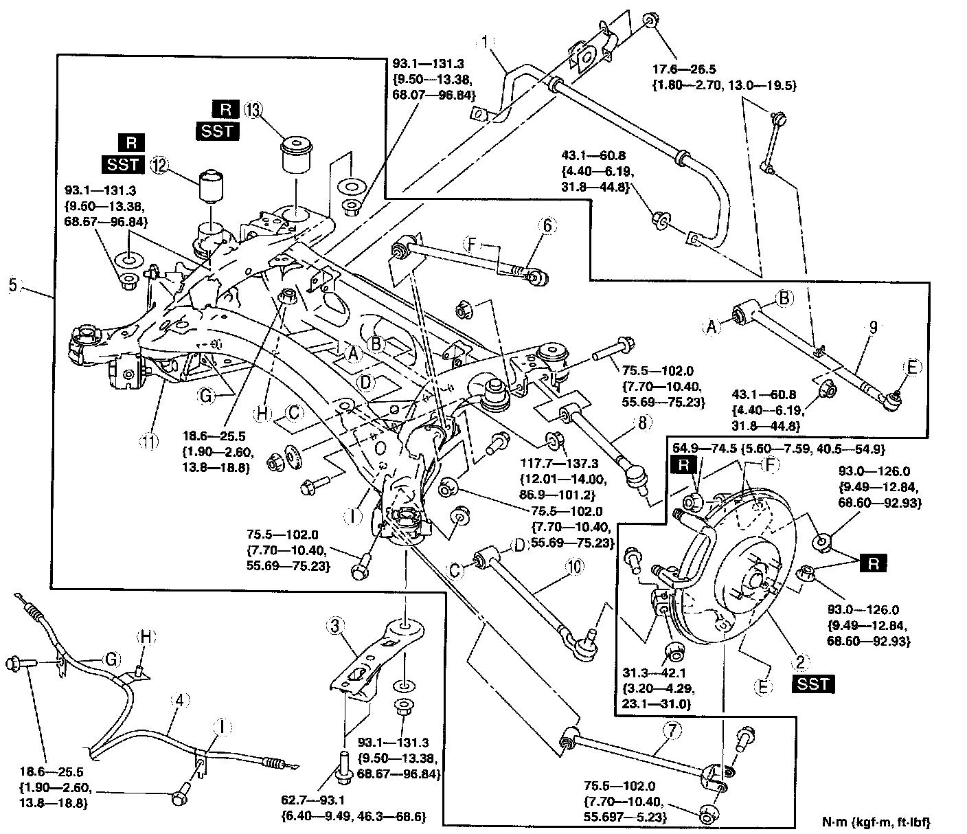
6. Remove in the order indicated in the table.
7. Install in the reverse order of removal.
8. Inspect the rear wheel alignment.
Rear Axle Component Removal Note
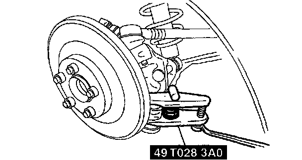
1. Support the knuckle using a jack.
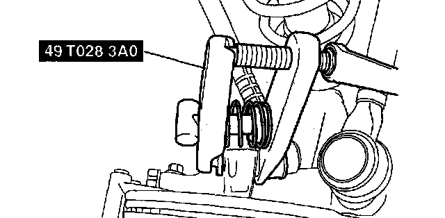
2. Using the SST, disconnect the rear trailing link (upper) ball joint.
3. Remove the rear trailing link (lower) outer bolt.
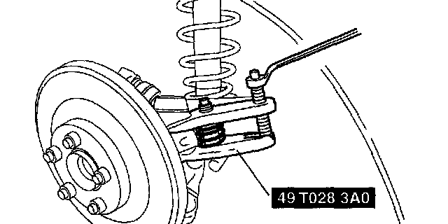
4. Using the SST, disconnect the rear lateral link (upper) ball joint.
5. Using the SST, disconnect the rear lateral link (lower) ball joint.
6. Remove the toe control link outer bolt.
7. Remove the shock absorber lower bolt.
8. Remove the rear axle component.
Rear Crossmember Component Removal Note
Warning:
^ Be sure that the crossmember component is securely supported by the jack. If not securely supported, the crossmember component could fall, resulting in serious injury or death, and damage to the vehicle.
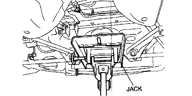
1. Support the rear crossmember with the jack, and remove the bolt.
2. Remove the rear crossmember component.
No.2 Bushing Removal Note
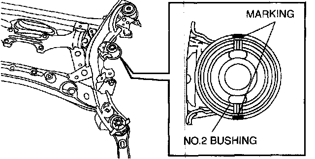
1. Mark the rear crossmember with the bushing hole aligned as shown in the figure.
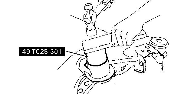
2. Remove the bushing using the SST.
No.3 Bushing Removal Note
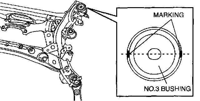
1. Mark the rear crossmember with the bushing hole aligned as shown in the figure.
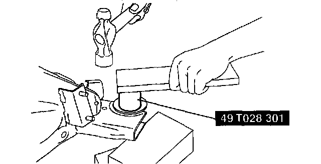
2. Remove the bushing using the SST.
No.3 Bushing Installation Note
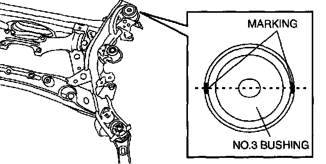
1. Install the new bushing according to the marking made during bushing removal.
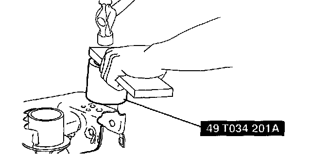
2. Press fit the bushing using the SST.
No.2 Bushing Installation Note
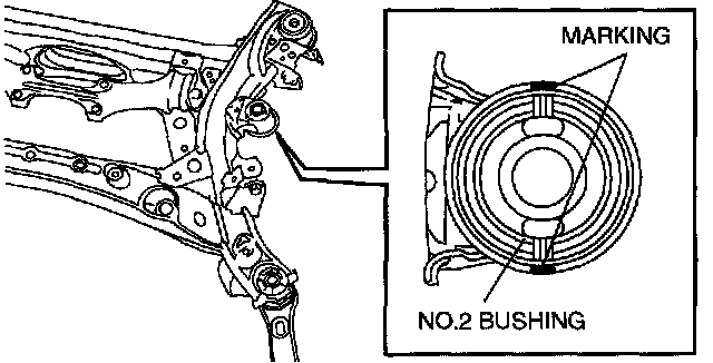
1. Install the new bushing according to the marking made during bushing removal.
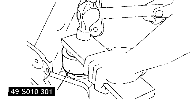
2. Press fit the bushing using the SST.