Oscilloscope Patterns and Waveforms
Inspection Using An Oscilloscope (Reference)NOTE: The duty ratio for the wave pattern can vary with the control conditions. Therefore determine comprehensively where the malfunction occurs among the input systems, output systems, and the PCM,
Fuel injector (FS, RS) control
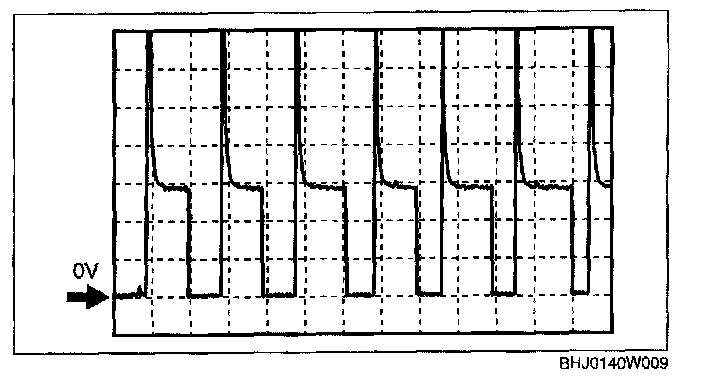
- Terminal connected:
FS: 2G (+) - Negative battery terminal
RS: 2D (+) - Negative battery terminal
- Oscilloscope setting: 5 V/DIV (Y): 5 ms/DIV (X), DC range
- Measurement condition: Racing after warm-up (no load)
Fuel injector (FP1, RP1) control
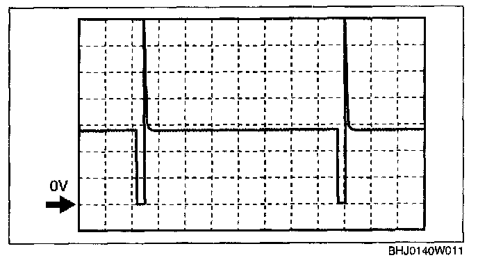
- Terminal connected:
FP1: 2M (+) - Negative battery terminal
RP1: 2J (+) - Negative battery terminal
- Oscilloscope setting: 5 V/DIV (Y): 10 ms/DIV (X), DC range
- Measurement condition: Idling after warm-up (no load)
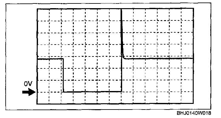
- Terminal connected:
FP1: 2M (+) - Negative battery terminal
RP1: 2J (+) - Negative battery terminal
- Oscilloscope setting: 5 V/DIV (Y): 10 ms/DIV (X), DC range
- Measurement condition: Cranking while the engine is cold. (ECT: Approx. 20 °C {68 °F})
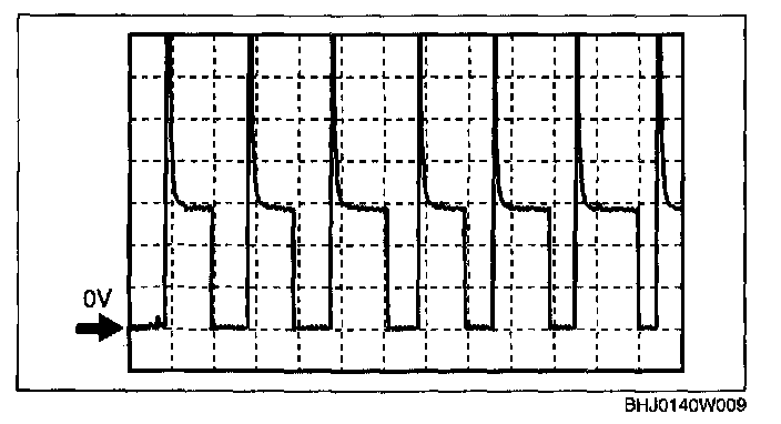
Fuel injector (FP2, RF2) control
- Terminal connected:
FP2: 3A (+) - Negative battery terminal
RP2: 3D (+) - Negative battery terminal
- Oscilloscope setting: 5 V/DIV (Y): 5 ms/DIV (X), DC range
- Measurement condition: Racing after warm-up (no load)