Recall - Interior Impact Non-Compliance
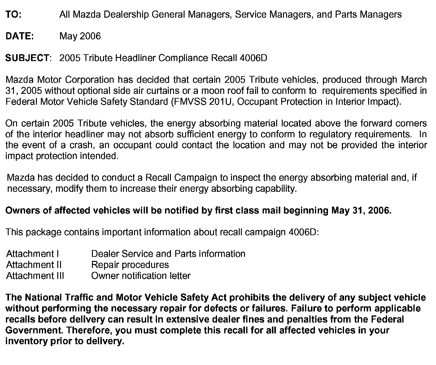
DEALER LETTER
CONDITION OF CONCERN
On certain 2005 Tribute vehicles, the energy absorbing material located above the forward corners of the interior headliner may not absorb sufficient energy to conform to regulatory requirements.

SUBJECT VEHICLES
OWNER NOTIFICATION
Mazda will notify U.S. owners by first class mail beginning May 31, 2006.

PARTS INFORMATION
PARTS ORDERING
Campaign labels are available in quantities of 50 per package by ordering through MStore.
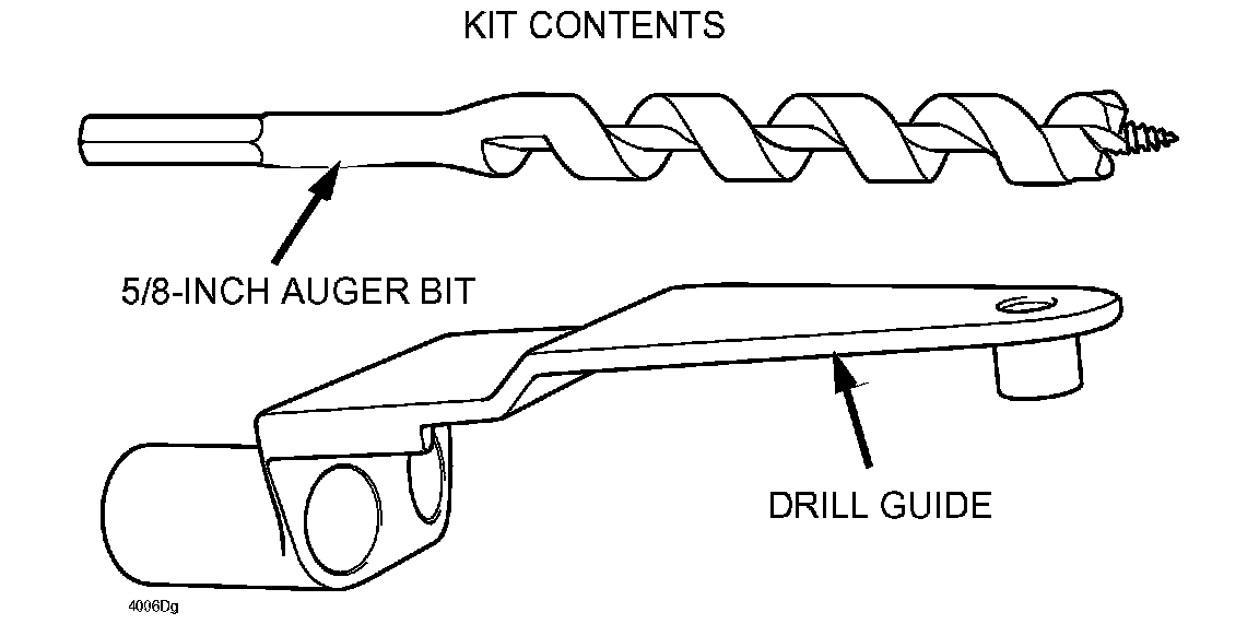
SPECIAL SERVICE TOOL

An initial shipment of a Drill Guide (Jig) and a 5/8" Auger Drill Bit will be shipped to dealers directly from the vendor beginning 5/26/06. Dealers should receive the special service tools by 5/30/06. Additional Drill Guides (Jigs) and 5/8" Auger Drill Bits can be ordered through M-Store for an additional cost. They cannot be ordered on the eMDCS Parts Ordering System. These parts are not inventoried at the PDCs.

WARRANTY CLAIM PROCESSING INFORMATION
RENTAL CAR
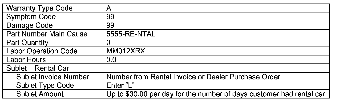
A rental car may be provided to the customer if eligible based on the terms and conditions of the Rental Car Reimbursement Program, policy 12.0. Rental car reimbursements are available only on 2001 and newer vehicles within the mileage and time limitations under the New Vehicle Limited Warranty. If the customer was placed in a rental car while the campaign was being completed, submit a separate claim/problem using the standard rental claim information. Rental expenses exceeding the two-day limit will require prior DCSM Authorization, as outlined in the Rental Car Reimbursement Program policy.
VERIFY THE VEHICLE NEEDS THE RECALL

1. Verify the vehicle is within the ranges:
If the vehicle is within the above range, go to step 2.
If vehicle is not within the above range, return it to inventory or the customer.
2. Perform a Warranty Vehicle Inquiry using your eMDCS System and inspect vehicle for an Authorized Modification Label RECALL 4006D attached to the vehicle's bulkhead.
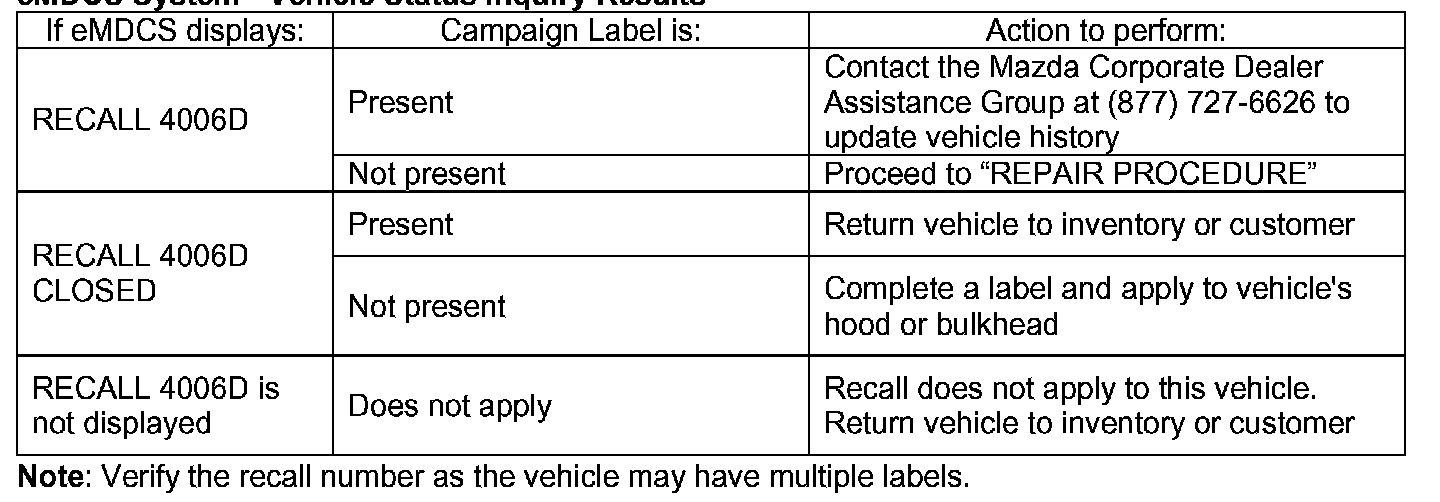
eMDCS System - Vehicle Status Inquiry Results
REPAIR PROCEDURES
A. VEHICLE INSPECTION PROCEDURE
1. Verify that the vehicle is within the following ranges:
- 2005 Tribute within the following VIN ranges: (built between Job #1 through March 31, 2005) 4F2YZ****5KM00003 - 4F2YZ****5KM62453
- If the vehicle is within the above ranges, proceed to Step 2.
- If the vehicle is not within the above range, return the vehicle to the customer or inventory.
2. Perform a Warranty Vehicle Inquiry using your eMDCS System and inspect vehicle for a Campaign Label Recall 4006D attached to the vehicle's hood. Refer to eMDCS System - Warranty Vehicle Inquiry Results table.
NOTE: Verify Recall number as the vehicle may have multiple recalls.
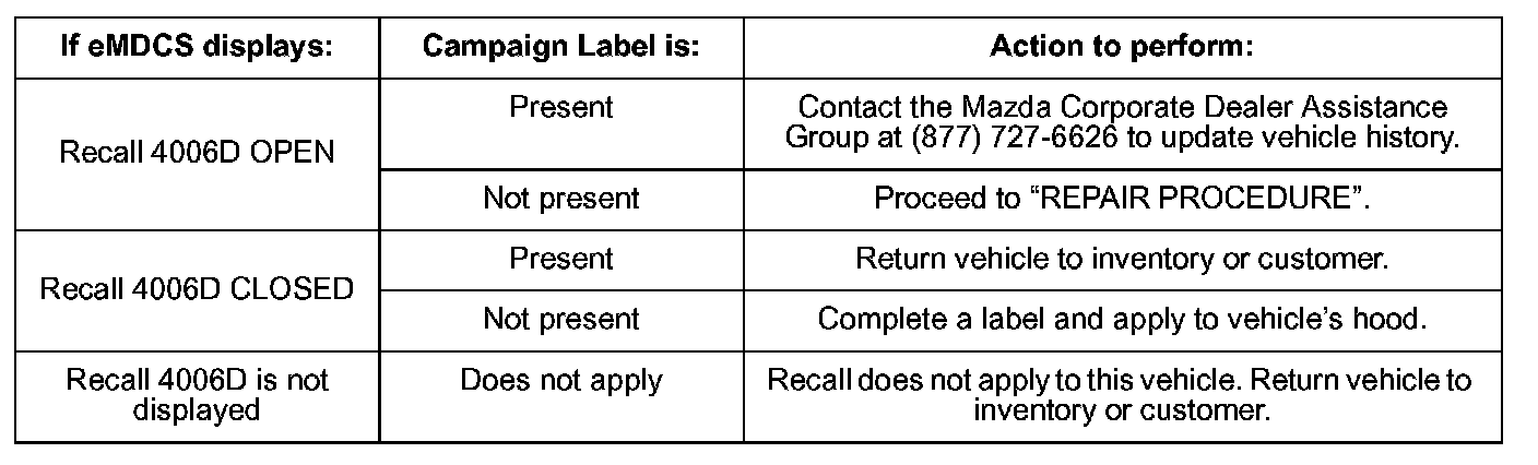
eMDCS System - Warranty Vehicle Inquiry Results
OVERVIEW
This program involves inspecting the structural foam blocks mounted at the front corners on the top of the headliner. If necessary, the foam blocks will be modified by drilling two (2) holes in each block with a supplied drill guide and auger drill bit.
The purpose of this modification is to bring the foam blocks into compliance with FMVSS 201, Occupant Protection in Interior Impact. Vehicles equipped with a moonroof or side air curtains are not involved.
B. REPAIR PROCEDURE
CAUTION: Failure to perform all disassembly steps as outlined increases the possibility of damaging the headliner.
CAUTION: Make sure your hands are clean before performing this repair.
NOTE: Although the headliner does not have to be removed to carry out the inspection or modification, a number of trim panels and components must be removed or repositioned in order to lower the front of the headliner for access. Performing all steps as outlined will position the headliner adequately for access to the repair area.
NOTE: If the vehicle is equipped with any aftermarket or dealer-installed options, such as a DVD player which interferes with adequately lowering the headliner, they must be removed.
DISASSEMBLY FOR INSPECTION:
NOTE: Perform the following steps on both sides of the vehicle.
1. Open the A-pillar assist handle bolt covers, then remove the bolts and the assist handles.
2. Remove the A-pillar trim panels.
3. At the B-pillars, remove the D-ring covers and safety belt bolts.
4. Remove the upper B-pillar bolt covers and bolts, then remove the B-pillar trim panels.
5. If equipped, remove the overhead console retaining screws and disconnect the electrical connector, then remove the console from the vehicle.
6. Remove the sunvisors and sunvisor clips. If equipped, disconnect the electrical connectors.
7. Open the rear seat overhead assist handle bolt covers, then remove the bolts and the assist handles.
8. Position the front and rear door weatherstrips down away from the headliner.
9. Allow the headliner to hang down loosely at the front corners. Do not pull down on the headliner or otherwise stress it, or damage may result.
INSPECTION:
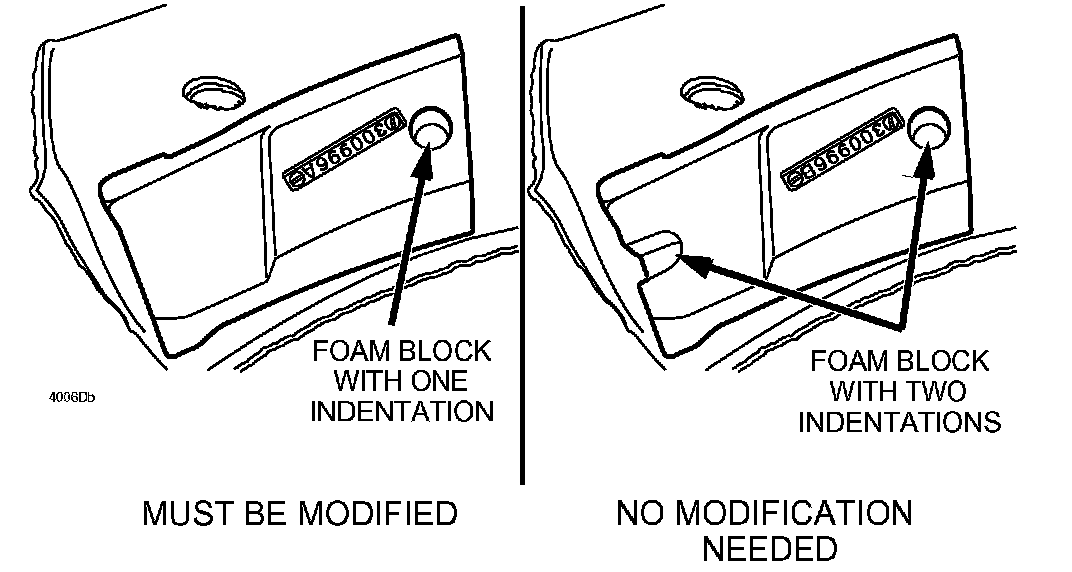
1. Without pulling the headliner down beyond its natural hanging rest position, carefully inspect the structural foam blocks mounted at the passenger and drivers side front corners on the top of the headliner to see if they have one (1) or two (2) indentations.
- If the blocks have two (2) indentations, no modification is required. Proceed to ASSEMBLY.
- If the blocks have only one (1) indentation, proceed to DISASSEMBLY FOR MODIFICATION.
DISASSEMBLY FOR MODIFICATION:
1. Remove the interior lamp lens.
2. Remove the two (2) screws and the interior lamp, then disconnect the electrical connector.
3. Proceed to FOAM BLOCK MODIFICATION.
FOAM BLOCK MODIFICATION:
1. Using fender covers, seat covers or suitable rags, cover the defroster and instrument panel ducts so no chips can fall into the heater plenum.
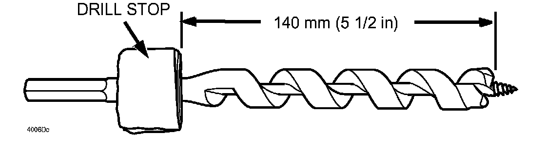
2. Install a drill stop or apply suitable tape onto the drill bit 140 mm (5 1/2 in) from the end of the cutting portion of the bit (not from the threaded tip).
CAUTION: The weight of the tool when positioned on the foam block increases the risk of headliner damage. Hold the headliner up when the tool is positioned on the foam block.
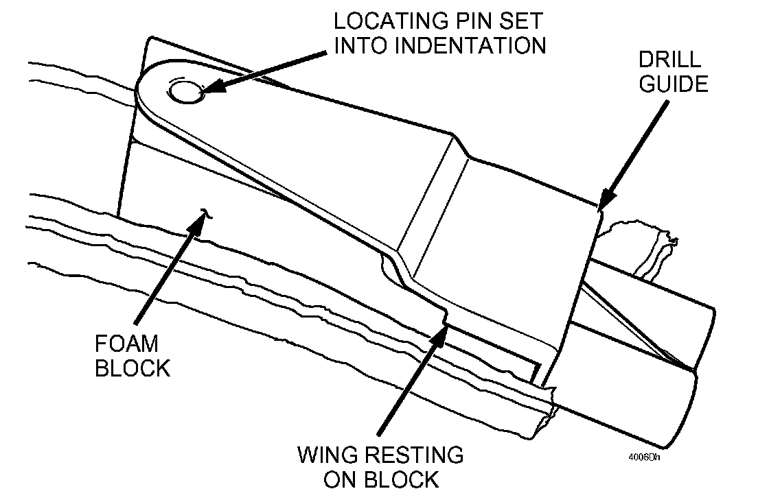
3. Starting on either side of the vehicle, position the supplied drill guide onto the foam block so that the locating pin is set into the indentation on top of the block and the "wings" are resting on either side of the block, preventing the guide from moving side-to-side.
WARNING: WEAR SAFETY GLASSES.
CAUTION: DO NOT USE an air-powered drill for this operation. Oil spray from the tool may damage the foam block or other interior trim.
CAUTION: Be sure to keep the drill motor at full speed and frequently clear the chips from the bit while drilling each hole. Bore the holes at a slow to moderate pace using light to moderate pressure on the drill. Attempting to bore the holes at a fast pace using excessive pressure on the drill or failing to clear the chips from the bit may cause the foam blocks to crack.
NOTE: Be sure to allow the drill motor to achieve full speed before attempting to bore the hole.
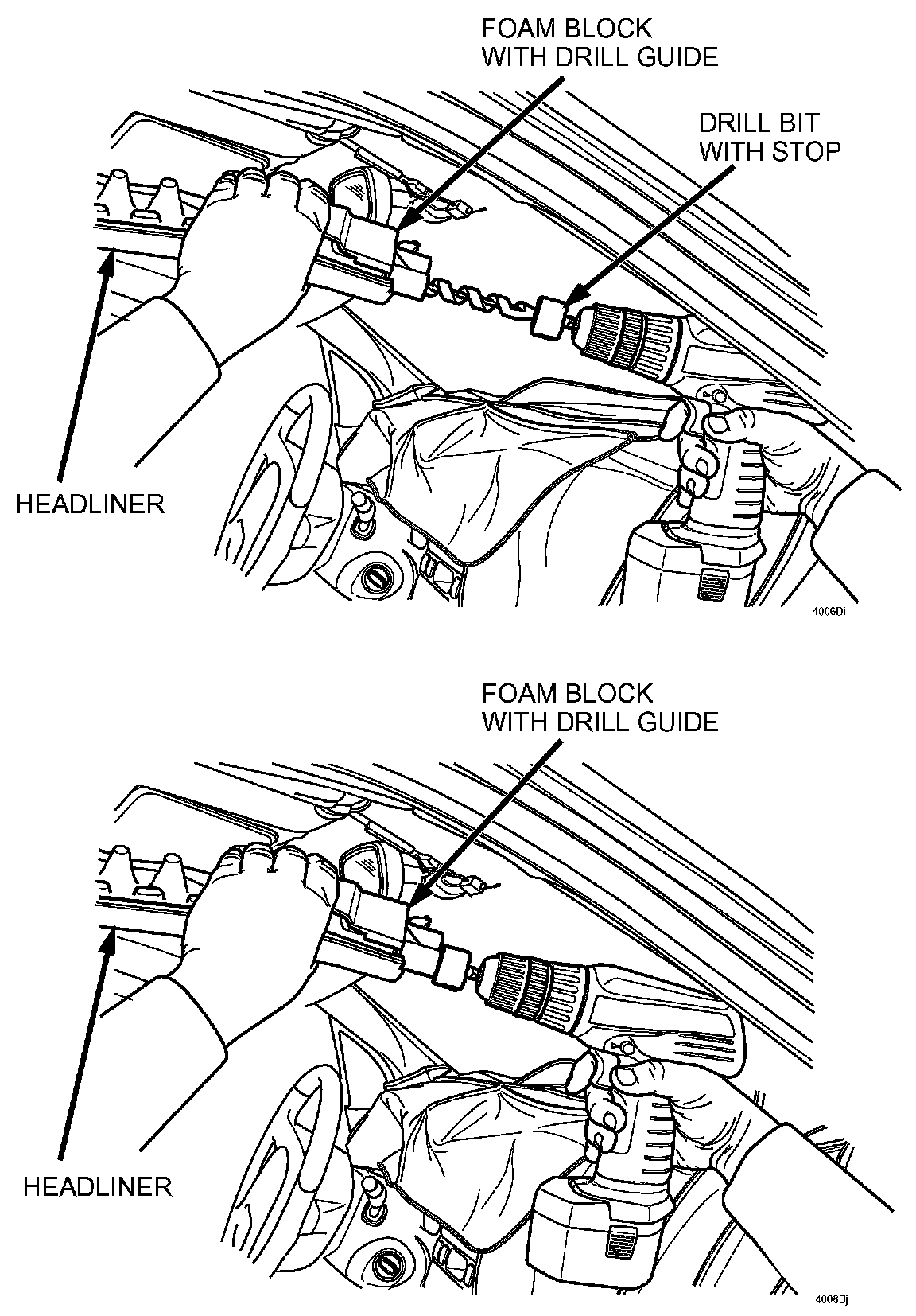
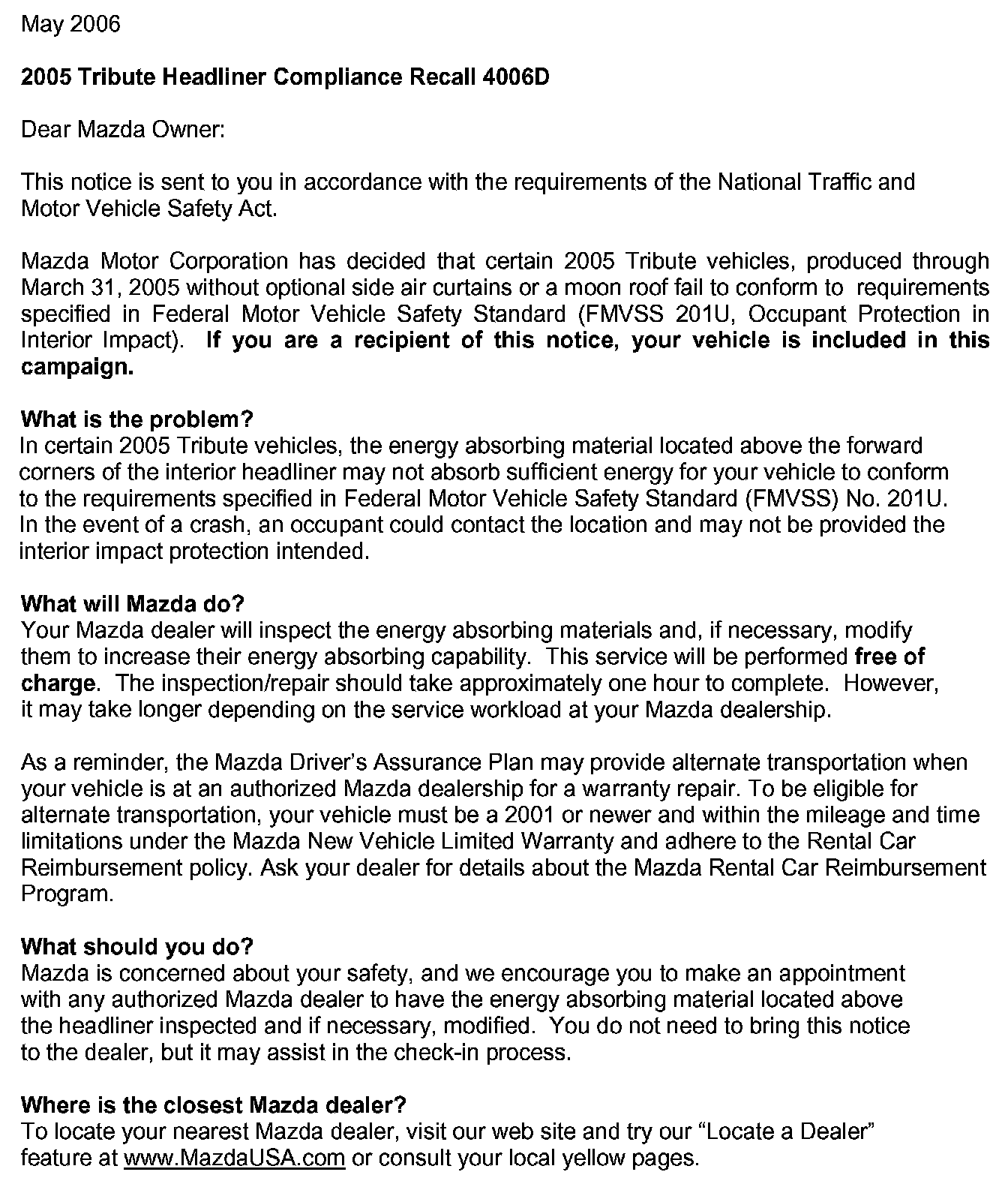
4. Drill the holes as follows:
A. Holding the drilling guide securely in place, position the drill bit in either of the two (2) guide holes.
B. Start the drill motor and allow it to achieve full speed.
C. Drill the hole at a slow to moderate pace, occasionally pulling the bit out to clear the chips.
D. Drill the hole to the proper depth using the stop on the bit as your depth gauge.
E. Drill the second hole in the same foam block in the same manner.
F. Repeat steps A E on the foam block on the other side of the headliner.
5. Thoroughly clean all foam chips from the vehicle. Remove the covers from the instrument panel and make sure no chips remain in the vehicle. Proceed to ASSEMBLY.
ASSEMBLY:
1. Position the B-pillar trim panels and install the bolts. Tighten to 7 Nm (62 lb-in), then install the bolt covers.
2. Position the safety belt and install the safety belt bolts at the B-pillar. Tighten to 53 Nm (39 lb-ft), then install the D-ring covers.
3. Install the A-pillar trim panels.
4. Install the passenger A-pillar assist handles and bolts. Tighten to 5 Nm (44 lb-in), then install the bolt covers.
5. Install the front and rear door weatherstrips.
6. Connect and install the overhead console, if equipped.
7. Install and connect the interior lamp and screws.
8. Install the interior lamp lens.
9. Install the sunvisors, connecting the electrical connectors if equipped, and the sunvisor clips.
10. Install the rear seat overhead assist handles and bolts. Tighten to 8 Nm (71 lb-in), then install the bolt covers.
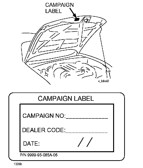
C. CAMPAIGN LABEL INSTALLATION
Complete an "Campaign Label" with the Recall number written on the sticker and affix it to the vehicle's hood.
Refer back to the illustration under "A. VEHICLE INSPECTION PROCEDURE"
OWNER LETTER