Assembly
TRANSAXLE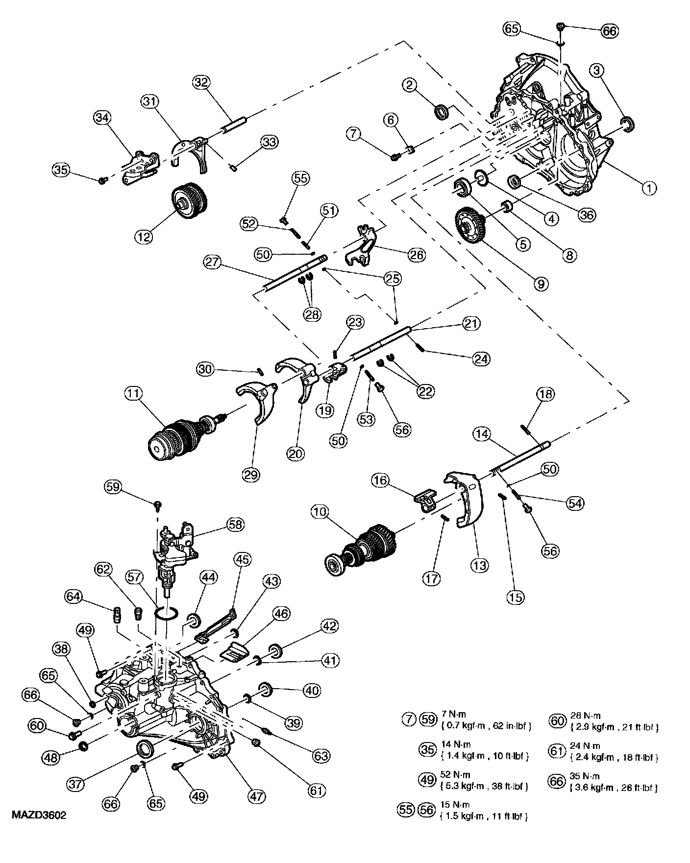
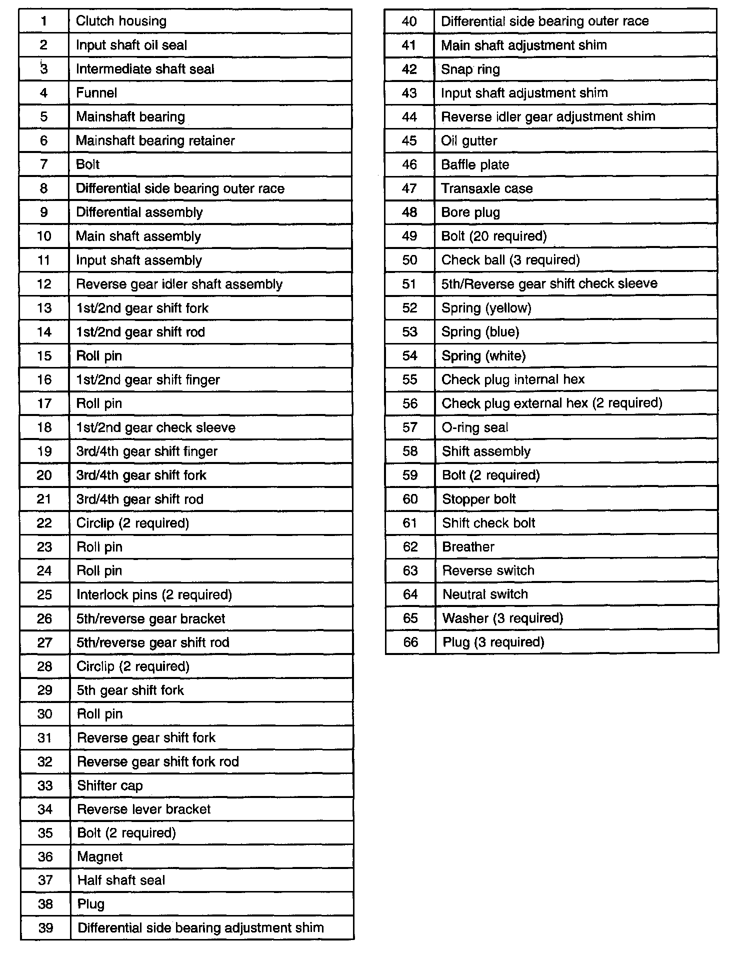
Assembly
Caution: Whenever the transaxle has been disassembled, the bearing preload must be adjusted. The input shaft, output shaft and differential bearing preload can be adjusted by selecting shims to insert between the bearing races and the case on the case side.
Caution: Assembly should only be carried out in a clean environment or damage to the transaxle may occur.
Caution: Be careful not to scratch the sliding face or mating faces or damage to the transaxle may occur.
Caution: Visually inspect all parts for any damage, deformation or abnormal wear. Replace any unsuitable parts with new parts only or damage to the transaxle may occur.
Caution: Do not work on the transaxle with cotton gloves, cotton threads could become dislodged and damage to the transaxle may occur.
Caution: Replace all retaining pins, oil seals and bearings with new parts or damage to the transaxle may occur.
Caution: Make sure to clean the old sealant from the mating threads of any sealed bolt or damage to the transaxle may occur.
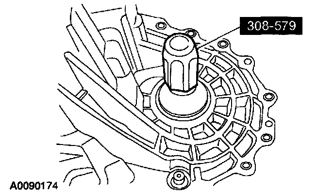
1. Using the special tools, install a new input shaft oil seal.
2. Using the special tools, install a new half shaft oil seal.
3. Position the oil channel, make sure that the rib is correctly positioned.
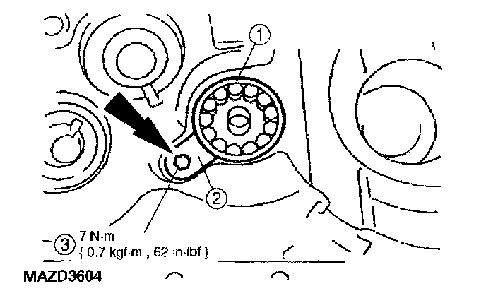
4. Install the mainshaft front bearing and retainer.
1. Install the mainshaft front bearing.
Note: The stamping on the bearing retainer is installed facing away from the clutch housing.
2. Position the retainer.
3. Install the bolt.
Caution: Do not exceed 120°C (248°F) or damage to the clutch housing may occur.
5. Heat the clutch housing to 100°C (212°F) and install the differential side bearing outer race.
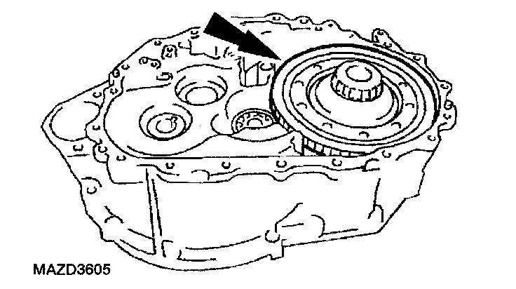
6. Install the differential.
Caution: Make sure to install the main shaft straight in. Failure to install the main shaft correctly may result in damage to the funnel on the clutch housing.
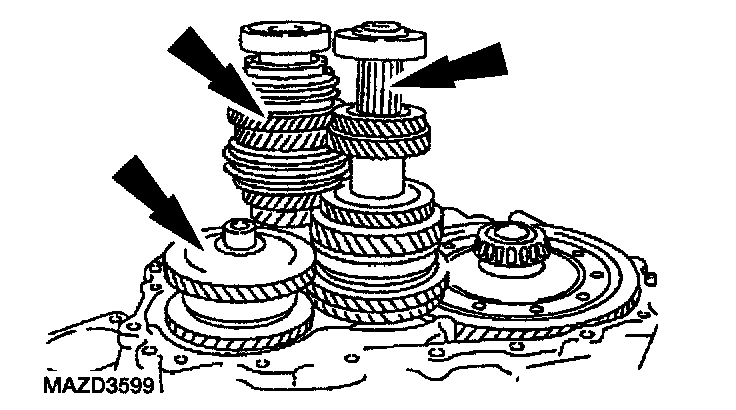
7. Install the input shaft, main shaft and reverse gear idler shaft as set.
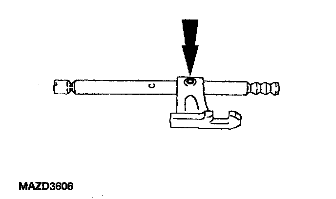
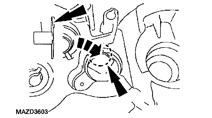
8. Position the 1st/2nd fork rod bracket on the 1st/2nd fork rod and install a new roll pin.
9. Install the 1st/2nd fork rod and the 1st/2nd shift fork and install a new roll pin.
10. Install the 1st/2nd shift check sleeve.
Note: Apply Vaseline to the interlock pin to hold it in place.
11. Install a interlock pin into the 3rd/4th fork rod.
12. Install the 3rd/4th bracket, 3rd/4th shift fork and the 3rd/4th fork rod.
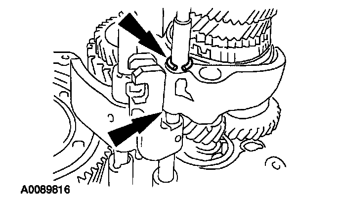
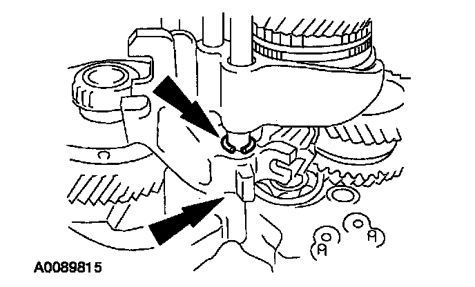
13. Install new circlips.
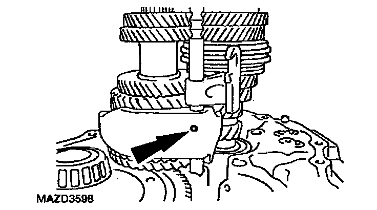
14. Install a new roll pin.
Caution: Make sure that the check balls remain in the correct location or damage to the transaxle may occur.
15. Install the two check balls.
16. Install the 5th/reverse bracket, the 5th shift fork and the 5th/reverse fork rod.
17. Install new circlips.
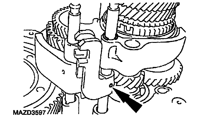
18. Install a new roll pin.
19. Install the reverse fork and the reverse fork rod.
20. Install the shifter cap on the reverse lever cam then lift the reverse gear shift fork and insert the cam part of the 5th/reverse gear bracket into the reverse level bracket.
21. Install the shifter cap on the reverse lever cam then lift the reverse gear shift fork and insert the cam part of the 5th/reverse gear bracket into the reverse level bracket.
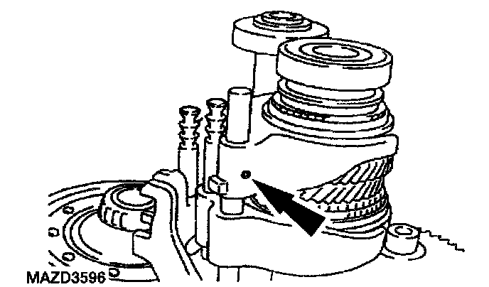
22. Install a check ball, 5th/reverse shift check sleeve, 5th/reverse check spring and a new check ball plug.
23. Install the magnet.
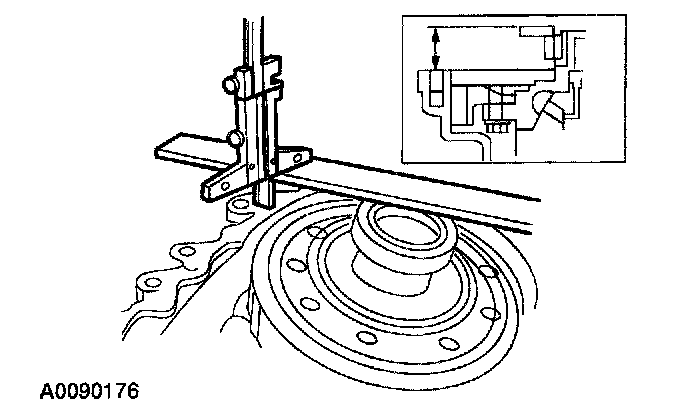
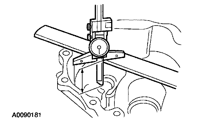
24. Using a depth micrometer and a straight edge, measure and record the depth from the mating surface of the transaxle case to the differential side bearing adjustment shim mounting surface. Record this measurement as L1.
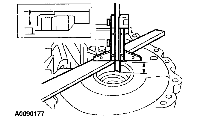
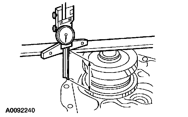
25. Using a depth micrometer and a straight edge, measure and record the depth from the mating surface of the clutch housing to the differential side bearing outer race outer surface. Record this measurement as L2.
1. Install the differential side bearing outer race on the differential bearing.
2. Holding the outer race in position using hand pressure, rotate the differential 5 times to seat the bearing races.
Note: Do not use more than 2 shims to achieve the desired shim thickness.
Note: Shims are available in thicknesses from 0.48 - 0.92 mm (0.0189 - 0.0366 inch) in 0.04 mm (0.00157 inch) increments.
26. Select the shims to allow a preload of 0.15 - 0.21 mm (0.0059 - 0.0083 inch) using the formula; shim thickness = (L1+L2) + Preload.
27. Install the differential side bearing adjustment shim.
Caution: Do not exceed 120°C (248°F) or damage to the transaxle case may occur.
28. Heat the transaxle case to 100°C (212°F) and install the differential side bearing outer race.
29. Install the differential oil seal.
Note: Apply Vaseline to the claw area to keep the baffle and oil gutter in place during case assembly.
30. Install the oil gutter and oil baffle in the transaxle case.
31. Temporarily install the main shaft, main shaft bearing and circlip.
32. Temporarily assemble the transaxle case.
33. Temporarily install and tighten the transaxle case bolts.
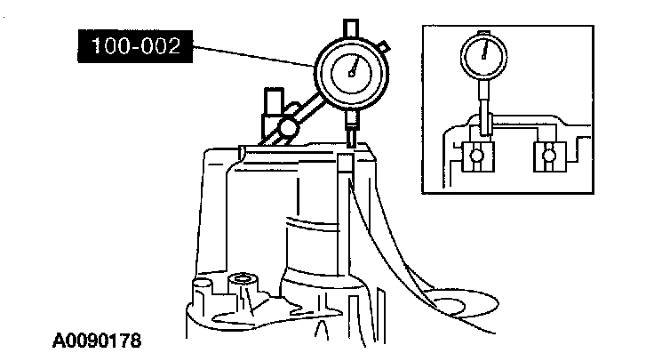
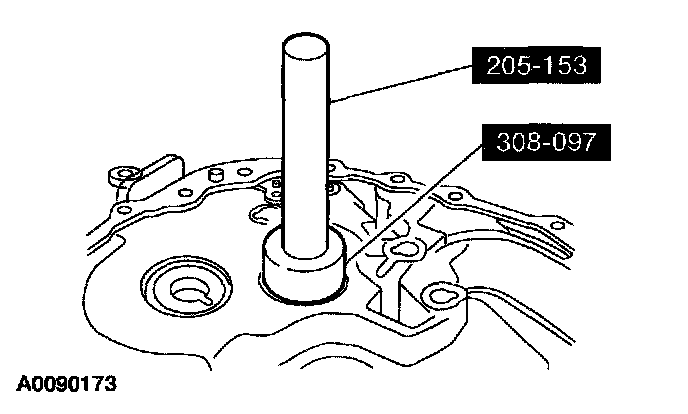
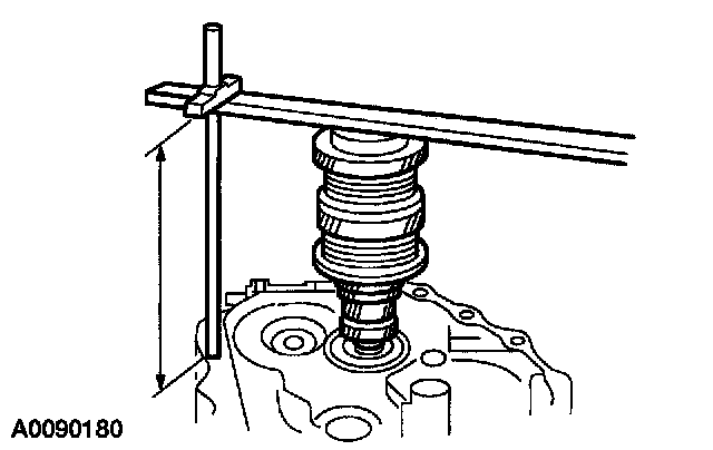
34. Using the special tool, measure and record the depth of the transaxle case to the main shaft bearing surface when the circlip is expanded and main shaft is raised to contact the transaxle case.
35. Release the circlip allow the main shaft to lower and engage the circlip, measure and record the depth of the transaxle case to the main shaft bearing surface.
Note: Do not use more than 1 shim to achieve the desired shim thickness.
Note: Shims are available in thicknesses from 0.44 - 1.08 mm (0.017 - 0.043 inch) in 0.04 mm (0.00157 inch) increments.
36. Select the shim to allow an end play of 0.00 - 0.06 mm (0.00 - 0.0024 inch).
37. Remove the transaxle case.
38. Install the differential side bearing adjustment shim.
39. Using a depth micrometer and a straight edge, measure and record the depth from the mating surface of the transaxle case to the input shaft adjustment shim mounting surface. Record this measurement as L1.
40. Using a depth micrometer and a straight edge, measure and record the depth from the mating surface of the clutch housing to the input shaft bearing outer race outer surface. Record this measurement as L2.
Note: Do not use more than 1 shim to achieve the desired shim thickness.
Note: Shims are available in thicknesses from 0.40 - 1.72 mm (0.016 - 0.068 inch) in 0.04 mm (0.00157 inch) increments.
41. Select the shims to allow an end play of 0.00 - 0.06 mm (0.00 - 0.0024 inch) using the formula; shim thickness = (L1-L2)-endplay.
42. Install the input shaft adjustment shim.
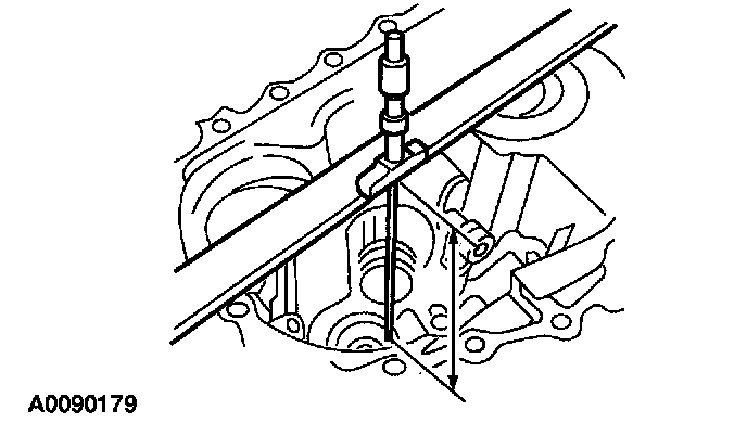
43. Using a depth micrometer and a straight edge, measure and record the depth from the mating surface of the transaxle case to the reverse idler shaft adjustment shim mounting surface. Record this measurement as L1.
44. Using a depth micrometer and a straight edge, measure and record the depth from the mating surface of the clutch housing to the reverse idler shaft bearing surface. Record this measurement as L2.
Note: Do not use more than 1 shim to achieve the desired shim thickness.
Note: Shims are available in thicknesses from 1.76 - 2.64 mm (0.069 - 0.104 inch) in 0.04 mm (0.00157 inch) increments.
45. Select the shims to allow an end play of 0.04 - 0.14 mm (0.001 - 0.005 inch) using the formula; shim thickness = (L1-L2)-endplay.
46. Install the reverse idler shaft adjustment shim.
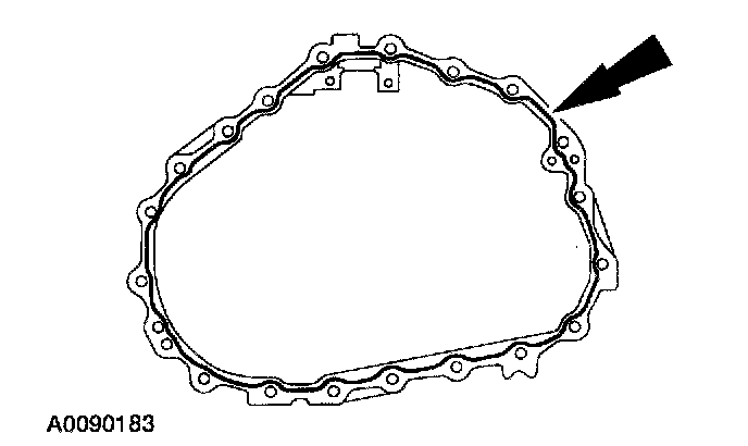
47. Apply a continuous bead of silicone gasket and sealant.
48. Spread the circlip and install the transaxle case.
Note: The black colored bolt must be installed new, in the correct position and tightened to the higher specification.
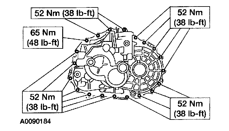
49. Install the 20 bolts and tighten to specification in a cross pattern.
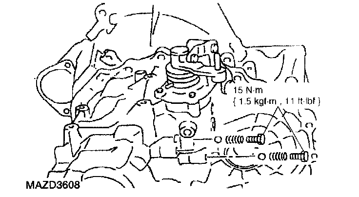
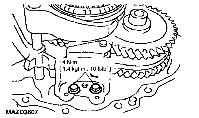
50. Install the two check balls, springs and new plugs.
51. Install a new O-ring on the control assembly.
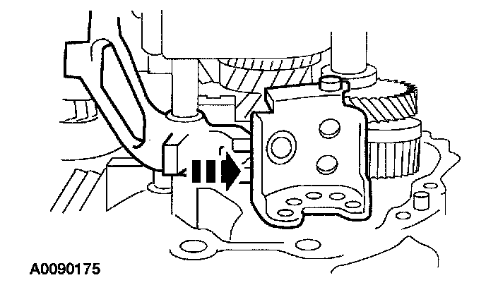
52. Install the control assembly.
53. Shift the transaxle to 2nd gear, lift the mainshaft and fully seat the snap ring into the mainshaft bearing.
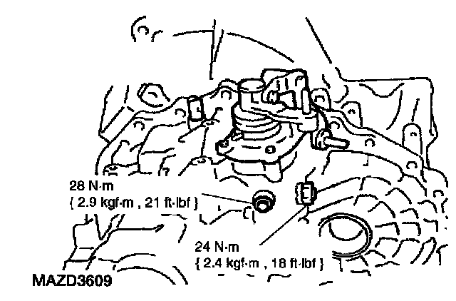
54. Install a new shift rod plug and a new stopper bolt.
55. Install a new welch plug and a new bore plug.
56. Install the reverse lamp switch.
Note: Install new gaskets on the drain and fill plugs.
57. Install the fill and drain plugs. Tighten the plugs to 35 Nm (3.6 kgf-m, 26 ft. lbs.).