Charging System: Description and Operation
CHARGING SYSTEMSee the Tribute Wiring Diagram for schematic information.
Principles of Operation
Functionality (Duratec engine only)
With the ignition switch in the ON position, voltage is applied through the warning indicator I circuit (LG/R) to the voltage regulator. This turns the regulator on, allowing current to flow from battery sense A circuit (B/Y) to the generator field coil. When the engine is started, the generator begins to generate alternating current (AC) which is internally converted to direct current (DC). This current is then supplied to the vehicle's electrical system through the output (B+) terminal of the generator.
Once the generator begins generating current, a voltage signal is taken from the generator stator and fed back to the regulator internally. This voltage feedback signal (typically half the battery voltage) is used to turn off the warning indicator.
With the system functioning normally, the generator output current is determined by the voltage of the A circuit. The A circuit voltage is compared to a set voltage internal to the regulator, and the regulator controls the generator field current to maintain the correct generator output.
The set voltage will vary with temperature and is typically higher in cold temperatures and lower in warm temperatures. This allows for better battery recharge in the winter and reduces the chance of overcharging in the summer.
Battery Positive Output (B+) Terminal Circuit 38 (B/0) (2.3L)
The generator output voltage is supplied through the battery positive output (B+) terminal circuit 38 (B/0) on the rear of the generator to the battery and electrical system.
Battery Positive Output (B+) Terminal Circuit 36 (Y/W) (3.0L)
The generator output voltage is supplied through the battery positive output (B+) terminal circuit 36 (Y/W) on the rear of the generator to the battery and electrical system.
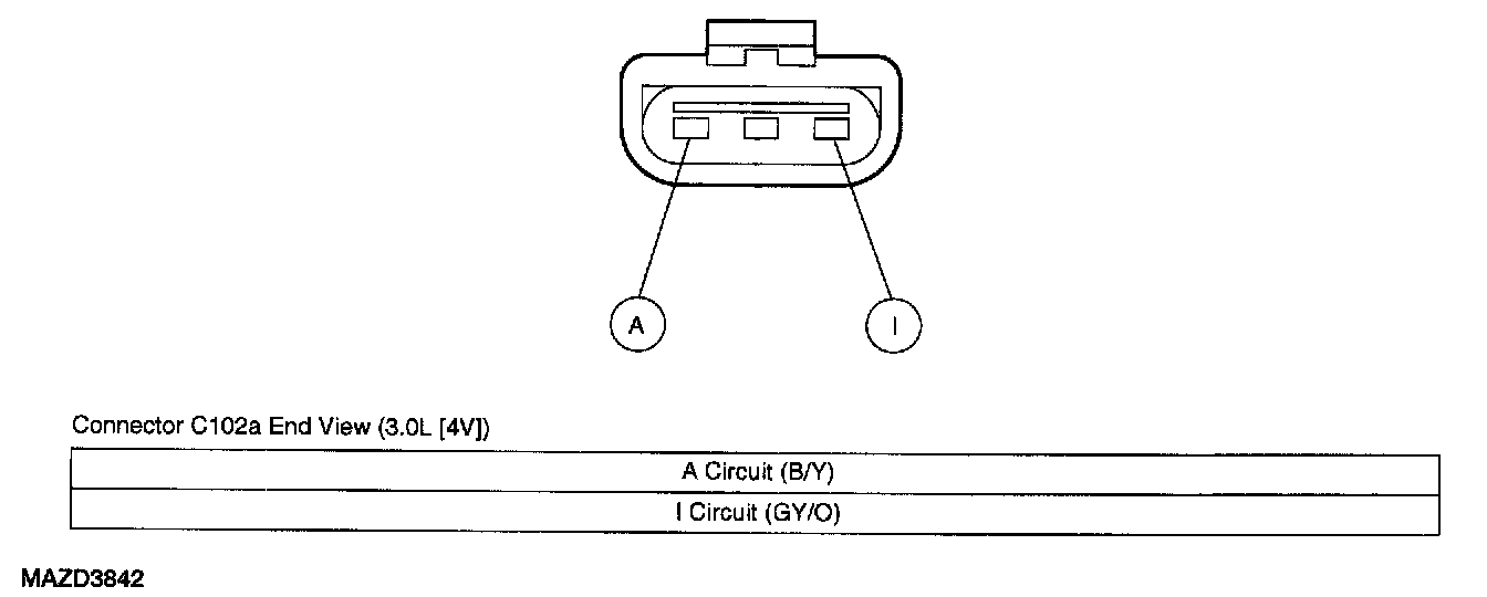
A Circuit 112 (B/Y)
This is the A terminal battery voltage sense circuit and it is used to sense battery voltage.
Circuit 921 (GY/0)
The generator monitor (GEN MON) circuit communicates the generator load and error conditions to the powertrain control module (PCM).
Circuit 920 (BR/W)
This is-the generator communication (GEN COM) circuit. The PCM determines the optimal voltage setpoint for the charging system and communicates this information to the voltage regulator through the GEN COM circuit.