Pinpoint Test 1
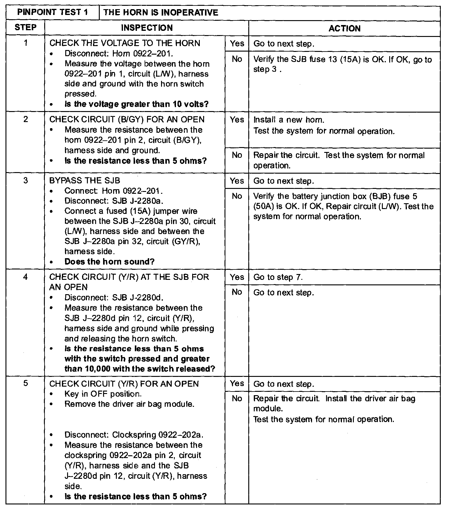
PINPOINT TEST 1: THE HORN IS INOPERATIVEStep 1-Step 5:
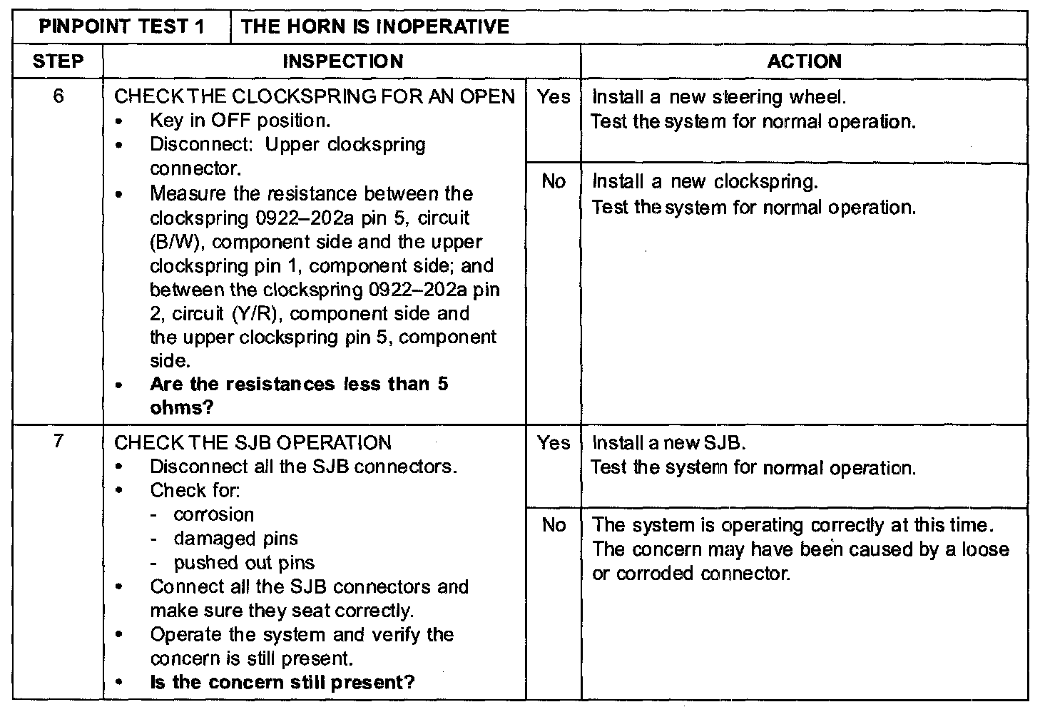
Step 6-Step 7:
Normal Operation
The horn relay control voltage and the horn relay switched voltage circuits are supplied by the smart junction box (SJB) fuse 13 (15 A) through circuit (GY/R). The horn relay (part of the SJB) is controlled by circuit (Y/R) through the clockspring to the horn switch (part of the steering wheel). When the horn switch is pressed, the horn relay control circuit (Y/R) is grounded through the clockspring and circuit (B/W). The horn relay is then energized causing voltage to be applied to circuit (L/W), enabling the horn to sound. Ground to the horn is supplied through circuit (B/GY).
Possible Causes
- Fuse(s)
- Circuit (Y/R) open
- Circuit (L/W) open
- Circuit (B/GY) open
- Circuit (B/W) open
- Horn
- Clockspring
- Horn switch (part of the steering wheel)
- SJB
CAUTION: Use the correct probe adapter(s) when making measurements. Failure to use the correct probe adapter(s) may damage the connector.