Evaporative Emissions System: Testing and Inspection
Purge Control System InspectionIf simulation function of the M-MDS is used:
1. Start the engine.
2. Disconnect the vacuum hose between the purge solenoid valve and the charcoal canister.
3. Put the finger to the purge solenoid valve and verify that there is no vacuum applied when the engine is cold.
- If there is a vacuum, inspect the following:
- Wiring harness and connectors (Purge solenoid valve-PCM terminal 1BC)
- Purge solenoid vale (stuck open)
4. Connect the M-MDS to the DLC-2 and verify that the DTC P0443 is shown. Perform the DTC inspection. (See DTC TABLE [MZI-3.5].) Diagnostic Trouble Code Descriptions
5. Select EVAPCP PID.
6. Increase the duty value of the purge valve to 50 % and inspect if the operation sound of the valve is heard.
- If the operation sound is heard, inspect for the loose or damaged vacuum hose. (Intake manifold-purge solenoid valve-charcoal canister)
- If the operation sound is not heard, perform the purge solenoid valve inspection.
7. Warm up the engine to normal operating temperature.
8. Monitor the EVAPCP PID using the M-MDS, and drive the vehicle approx. 2,000 rpm for 30 sec. or more.
- If the EVAPCP PID is 0 %, inspect the following.
- MAR APP1, APP2, APP3, TP_REL and LOAD PIDs.
If simulation function of the M-MDS is not used:
1. Start the engine.
2. Disconnect the vacuum hose between the purge solenoid valve and the charcoal canister.
3. Put the finger to the purge solenoid valve and verify that there is no vacuum applied when the engine is cold.
- If there is a vacuum, inspect the following:
- Wiring harness and connectors (Purge solenoid valve-PCM terminal 1BC)
- Purge solenoid vale (stuck open)
4. Connect the M-MDS to the DLC-2 and verify that the DTC P0443 is shown. Perform the DTC inspection. (See DTC TABLE [MZI-3.5].) Diagnostic Trouble Code Descriptions
5. Access EVAPCP and ECT PIDs.
6. Verify that the ECT PID is more than 78 °C {173 °F}.
- If the ECT PID reading indicates less than 78 °C {173 °F}, perform the ECT inspection.
7. Set the vehicle on the dynamometer or chassis roller.
WARNING: When the dynamometer or chassis roller is operating, there is a possibility that the operator may come into contact with or be caught up in the rotating parts, leading to serious injuries or death. When performing work while the dynamometer or chassis roller is operating, be careful not to come into contact with or caught up in any of the rotating parts.
8. Drive the vehicle approx. 2,000 rpm for 30 sec. or more.
- If there is no vacuum, inspect the following:
- Wiring harness and connector (Main relay-purge solenoid valve-PCM terminal 1BC)
- Purge solenoid valve
- MAF, APP1, APP2, APP3, TP_REL and LOAD PIDs
- If there is vacuum, inspect the following:
- Vacuum hose (Purge solenoid valve-charcoal canister)
Evaporative Emission (EVAP) System Leak Inspection
- To verify that the problem has been fixed properly after repairs, the run drive cycle or EVAP system leak inspection must be performed.
EVAP system leak inspection using leak tester
1. Perform the following SST (EVAP System Tester 134-01049) self-test:
NOTE: If the tester does not work correctly during the self-test, refer to the tester operators manual for a more detailed self-test procedure.
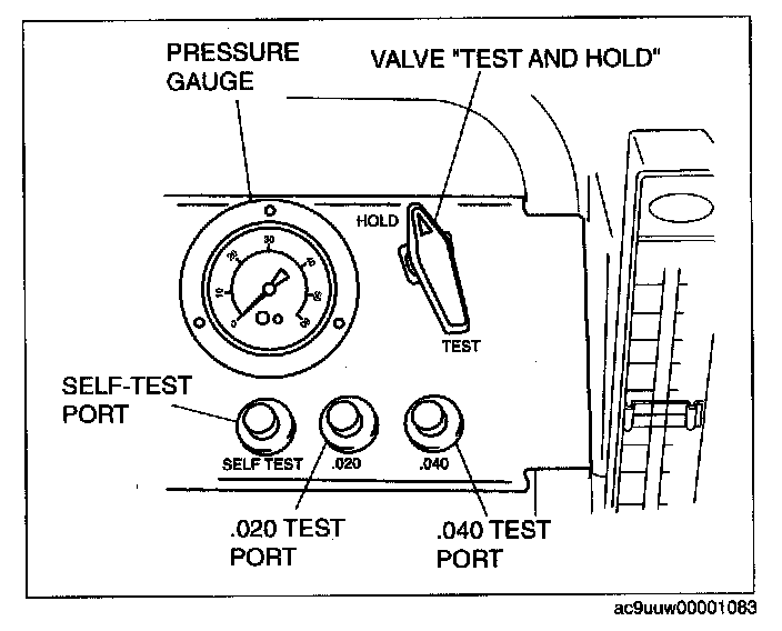
1. Verify that the control valve on the panel is in the HOLD position then open the nitrogen bottle valve.
2. Connect the vehicle interface hose (part of the SST) to the SELF-TEST port located on the control panel. Hand tighten the fitting. (Do not overtighten.)
3. Turn the control valve to the TEST position.
4. The gauge should read 331-381 mm {13-15 in} of water.
- If the gauge is not reading in this range, adjust the pressure by turning the black knob on the low pressure regulator at the nitrogen bottle.
5. Turn the control valve to the HOLD position.
6. Verify that the gauge holds pressure and that the flow meter reads no flow.
- If there is no drop in pressure and no flow, the tester passes the self-test.
- If the gauge leaks down, refer to the tester operators manual.
2. Connect the SST to the vehicle.
1. Verify that the control valve on the panel is in the HOLD position then open the nitrogen bottle valve.
2. Remove the fuel-filler cap from the vehicle.
- If the fuel-filler cap is not a MAZDA part or equivalent, replace it.
NOTE: INSPECT FUEL FILLER CAP AND FILLER NECK
- Visually inspect for damage, insufficient sealing, rust, cracks or warps for filler cap and fiber neck.
- Repair or replace if necessary.
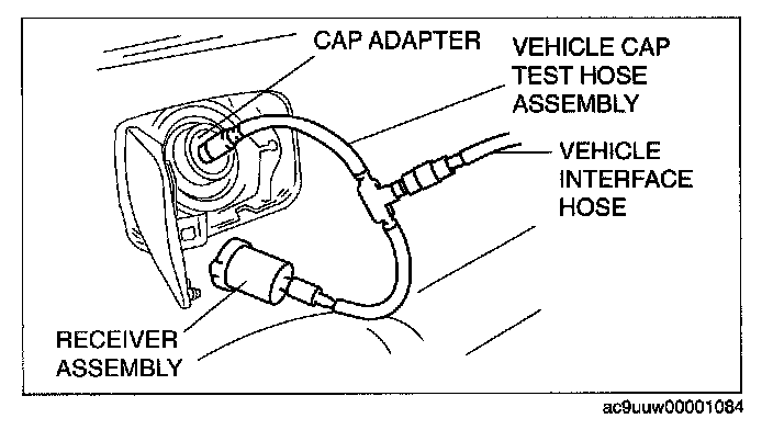
3. Connect the receiver assembly (SST: AKS441130) to the vehicle cap test hose assembly (part of the SST) and the fuel-filler cap from the vehicle.
4. Connect the cap adaptor (SST: AKS441131) to the vehicle cap test hose assembly (part of the SST) and to the fuel-filler neck.
5. Connect the vehicle interface hose (part of the SST) to the center fitting of the vehicle cap test hose assembly (part of the SST).
3. Connect the M-MDS to the DLC-2.
4. Turn the ignition switch to the ON position (Engine off).
5. Request the PCM on-board device control (Mode 08) using the M-MDS to close the canister vent value.
NOTE: The canister vent value is closed for 10 min unless the following any actions are done:
- The engine is started.
- The ignition switch is turned off position.
6. Make sure the control valve on the 134-01049 is in the HOLD position and that the valve on the cylinder of nitrogen gas is open.
7. Turn the control valve to the open position and let the system fill. You should note a drop in the gauge pressure along with the flow meter being pegged at maximum flow for several minutes depending on how full or empty the fuel tank is, and how long it takes to completely fill and pressurize the evaporative emissions system hoses.
8. If the gauge and the flow meter do not settle to a measurable level after 2-3 min, then refer to the Mazda Workshop Manual to verify that the canister vent valve is properly closed. If canister vent valve is properly closed. The EVAP system has large leakage. Check for leakage and repair as necessary.
9. Verify the pressure gauge and flow meter reading to determine if there is an evaporative emissions leak:
NO EVAPORATIVE LEAK:
- The flow meter registers "zero flow" and the pressure gauge returns to the pre-set pressure of 356 mm {14 in} of water (H2O).
EVAPORATIVE LEAK:
- The pressure does not return to the preset level of 356 mm {14 in} of water (H2O) when measuring the flow. See "SETTING LEAK STANDARD FOR TESTING" (0.020 to 0.040 inch H2O) of the Evaporative Emissions Tester operators manual (134-01067).
NOTE: Turn the control valve to the HOLD position then disconnect the SST.