Park Gear: Service and Repair
PARK SYSTEM REMOVAL / INSTALLATIONRemoval
1. With the vehicle in neutral, position it on a hoist.
2. Remove the digital transmission range (TR) sensor.
3. Remove the oil pan and oil strainer.
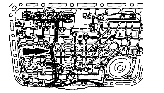
4. Unclip the wire loom guide and protector.
^ Lift up on wire harness guide and protector and disengage the retaining pins from the solenoid clamps.
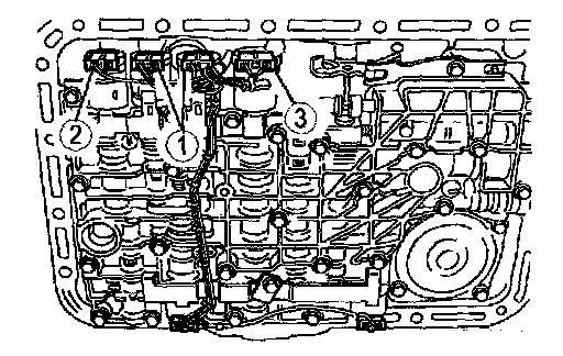
5. Disconnect the 6 solenoid electrical connectors.
(1) Disconnect the (1) SSA, SSB, SSC and SSD electrical connectors.
(2) Disconnect the (2) torque converter clutch (TCC) solenoid electrical connector.
(3) Disconnect the (3) electronic pressure control (EPC) solenoid electrical connector.
Caution:
^ The TCC solenoid and converter modulator valve may pop out of its bore. This may damage the solenoid or converter modulator valve.
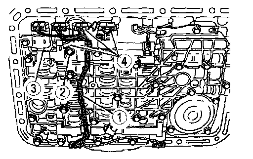
6. Remove the EPC, SSB, and SSD solenoids.
(1) Remove the wire harness.
(2) Remove the solenoid clamp bolts.
(3) Remove the solenoid clamp.
(4) Remove the EPC, SSB, and SSD solenoids.
Caution:
^ Do not pry on the other wires or damage the connector case surface.
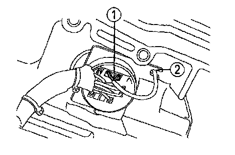
7. Disconnect the turbine shaft speed (TSS) sensor electrical connector from the 16 pin transmission case electrical connector.
(1) Disconnect the TSS sensor electrical connector.
(2) Remove from the TSS sensor wire locator.
Caution:
^ Do not overstretch the retaining spring.
8. Remove the 16 pin transmission case electrical connector retaining spring.
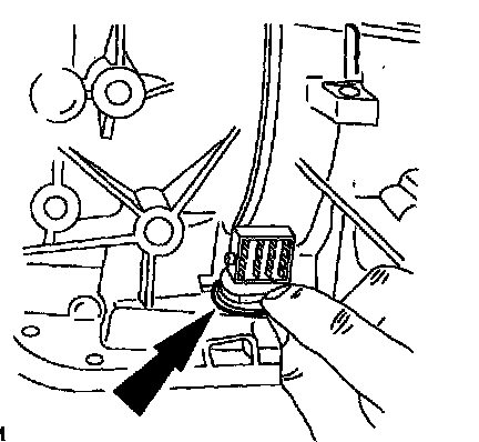
Caution:
^ Do not damage the connector or harness.
9. Remove the 16 pin transmission case electrical connector.
(1) Compress the tabs on the 16 pin transmission case electrical connector.
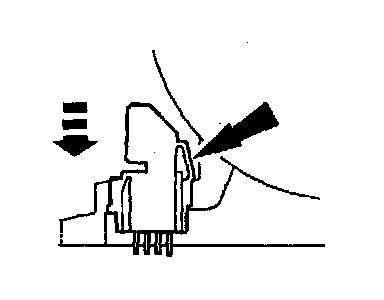
10. Push the 16 pin transmission case electrical connector out of transmission case.
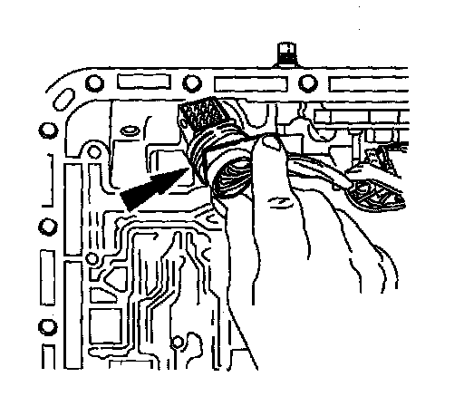
Caution:
^ To avoid damage, make sure the wrench does not strike the manual valve inner lever pin.
11. Remove the manual valve inner lever nut.
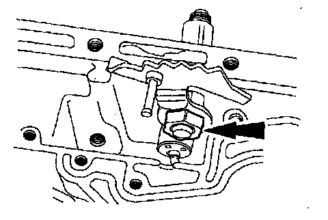
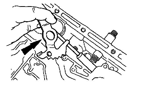
12. Remove the manual valve inner lever and parking lever actuating rod.
13. Remove the rear propeller shaft.
14. If equipped, remove the transfer case.
Note:
^ If damage is found to the parking gear, the transmission must be removed and disassembled.
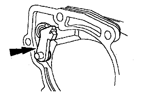
The parking pawl, parking pawl return spring and parking pawl shaft may fall out during removal of the extension housing.
15. Remove the extension housing. Discard the extension housing gasket.
16. Inspect the parking pawl, parking pawl return spring and the parking pawl shaft. Replace if required.
Installation
Caution:
^ Make sure the parking lever actuating rod is correctly seated into the case parking rod guide cup. Verify that the output shaft is locked in the PARK position.
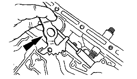
1. Align the flats of the manual valve inner lever with the flats on the manual control lever shaft. Install the manual valve inner lever and parking lever actuating rod onto the manual control lever shaft.
Caution:
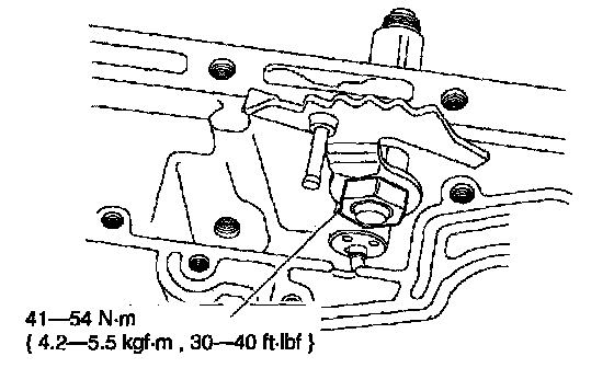
^ Do not bend the manual valve inner lever pin.
2. Install the manual valve inner lever nut.
3. Install new extension housing gasket and install the extension housing.
4. If equipped, install the transfer case.
5. Install the rear propeller shaft bolts.
Note:
^ Make sure the tab is in the lock position.
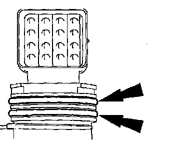
Install new O-rings on the 16 pin transmission case electrical connector.
6. Install the 16 pin transmission case electrical connector.
^ Lubricate the 16 pin transmission case electrical connector O-rings with petroleum jelly.
Caution:
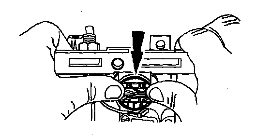
^ Align the slot on the TSS sensor electrical connector with the slot in the 16 pin transmission case electrical connector.
7. Press the 16 pin transmission case electrical connector through the case until a click is heard.
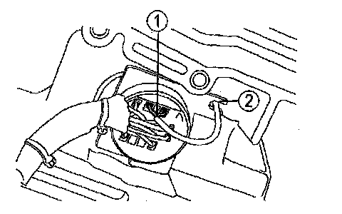
8. Install the TSS sensor wire.
(1) Install the TSS sensor wire into 16 pin transmission case electrical connector.
(2) Install the TSS sensor wire into locator.
Caution:
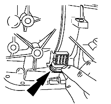
^ Do not overstretch the retaining spring.
9. Install the 16 pin transmission case electrical connector retaining spring.
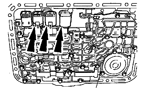
10. Install the EPC, SSB, and SSD solenoids.
Caution:
^ The solenoid clamp must be installed in the TCC and EPC solenoid grooves, shift solenoid pockets and the No. 204 plug.
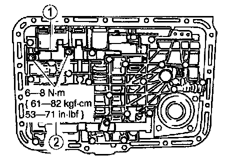
11. Install the solenoid clamp.
(1) Position the solenoid clamp on the main control valve body.
(2) Install the solenoid clamp bolts.
12. Connect the TCC, SSB, SSD, and EPC solenoid electrical connectors.
Caution:
^ Excessive pressure may break the retaining pins.
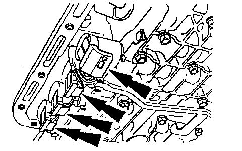
13. Install the wire loom guide and protector.
^ Align the retaining pins to the holes in the solenoid clamps and gently press in the wire loom guide and protector.
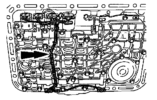
14. Install the oil strainer and a new oil pan gasket.
15. Install the digital TR sensor.
16. Fill transmission to proper fluid level and check for proper transmission operation.