Brake Fluid Pressure Sensor/Switch: Testing and Inspection
BRAKE FLUID PRESSURE SENSOR INSPECTION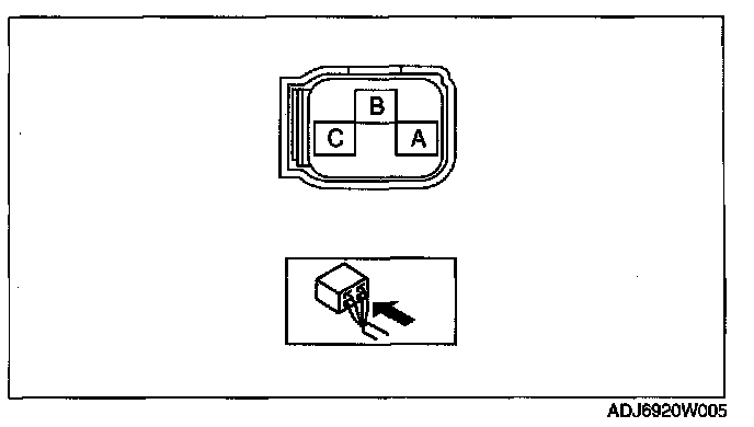
1. Turn the ignition switch to the ON position, then measure the voltage between brake fluid pressure sensor terminal C and ground.
^ If there is any malfunction, inspect the wiring harness between brake fluid pressure sensor terminal C and DSC HU/CM terminal C, then repair or replace if necessary.
Standard voltage
4.75-5.25 V
2. Measure the voltage between brake fluid pressure sensor terminal A and the ground.
^ If there is any malfunction, inspect the wiring harness between brake fluid pressure sensor terminal A and DSC HU/CM terminal E, then repair or replace if necessary.
Standard voltage
0 V
3. Turn the ignition switch off.
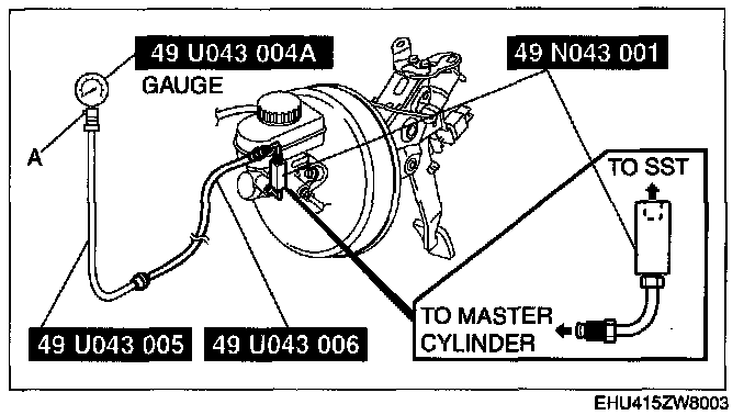
4. Install the SSTs to the master cylinder.
Note: Install the SST (49 D043 002 or 49 N043 001) to the master cylinder using a commercially available flare nut wrench.
- Flare nut across flat: 12 mm 10.47 inch)
5. Bleed the air from the SSTs and the brake line. (Bleed air from the SSTs through air bleeding valve A.)
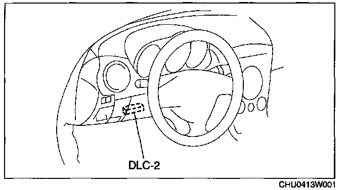
6. Connect the M-MDS to the DLC-2.
7. Select the MCYLI P PID.
8. Start the engine.
9. Depress the brake pedal, and confirm that the fluid pressure value of the SST (Gauge) and the value shown on the MMDS are equal.
^ If the fluid pressures are different, replace the DSC HU/CM.