Initial Inspection and Diagnostic Overview
Inspection and VerificationNote
^ If a new anti-lock brake system (ABS) module or hydraulic control unit (HCU) is installed, it must be configured. Follow the scan tool directions.
1. Verify the customer concern.
2. Verify the stoplamps operate correctly by applying and releasing the brake pedal with the ignition switch in the OFF position. If the stoplamps do not operate correctly, see STOPLAMPS. If the stoplamps operate correctly, proceed to the next step.
3. Verify that the PRNDL operates correctly on the instrument cluster. If the PRNDL does not operate correctly, see INSTRUMENT CLUSTER. If the PRNDL operates correctly, proceed to the next step.
4. Visually inspect for obvious signs of mechanical or electrical damage.
Visual Inspection Chart
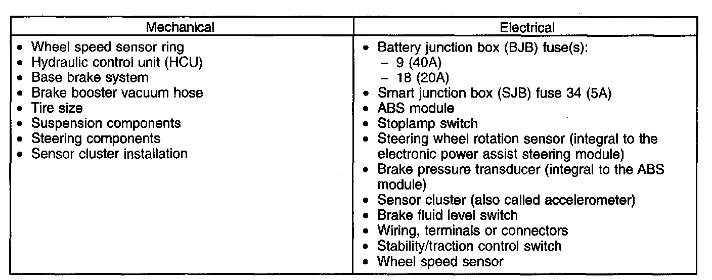
5. If an obvious cause for an observed or reported concern is found, correct the cause (if possible) before proceeding to the next step.
6. If the cause is not visually evident, connect the scan too( to the data link connector (DLC).
Note
^ Make sure to use the latest scan tool software release.
7. If the scan tool does not communicate with the VCM:
^ check the VCM connection to the vehicle.
^ check the scan tool connection to the VCM.
^ See PINPOINT TEST 14: NO POWER TO THE SCAN TOOL to diagnose no communication with the scan tool.
Note
^ The vehicle communication module (VCM) LED prove out confirms power and ground from the DLC are provided to the VCM.
8. If the scan tool does not communicate with the vehicle:
^ verify the ignition key is in the ON position.
^ verify the scan tool operation with a known good vehicle.
^ See PINPOINT TEST 1: THE PCM DOES NOT RESPOND TO THE SCAN TOOL OR NO HIGH SPEED CONTROLLER AREA NETWORK (HS-CAN) COMMUNICATION to diagnose no response from the PCM.
9. Carry out the network test.
^ If the scan tool responds with no communication for one or more modules, see SYMPTOM TROUBLESHOOTING CHART - COMMUNICATIONS NETWORK.
^ If the network test passes, retrieve and record continuous memory DTCs.
10. Clear the continuous DTCs and carry out the self-test diagnostics for the ABS module.
Note
^ The vehicle must be at a complete standstill while carrying out the self-test. Any movement of the vehicle during the self test may result in false DTCs being set.
11. If the DTCs retrieved are related to the concern, go to ABS Module DTC Chart. See ANTI-LOCK BRAKE SYSTEM (ABS) DTC CHART. For all other DTCs, see DIAGNOSTIC TROUBLE CODE (DTC) CHART - B, C AND U CODES.
12. If no DTCs related to the concern are retrieved, see SYMPTOM TROUBLESHOOTING CHART - ANTI-LOCK BRAKE SYSTEM (ABS).
Note
^ Always retrieve the continuous DTCs after running the self-test.
Note
^ For a complete master list of DTCs, see DIAGNOSTIC TROUBLE CODE (DTC) CHART - B, C AND U CODES.
Note
^ If DTC B2900, C1805 and U0001 are set at the same time, diagnose the concern for U0001 first.