Pinpoint Test 1
PINPOINT TEST 1: BOTH REVERSING LAMPS ARE INOPERATIVENormal Operation
Voltage is supplied from the battery junction box (BJB) fuse 35 (20 A) to the coil side of the reversing lamps relay through circuit (Y/GY). The reversing lamps relay switch side is supplied voltage by the BJB fuse 7 (10 A) through circuit (W/R). The reversing lamps relay coil ground is controlled by the digital transaxle (TR) sensor (automatic transaxle) or the reversing lamp switch (manual transaxle) through circuit (L/W). When the transaxle is in REVERSE (R), the digital TR sensor or the reversing lamp switch completes the ground path through circuit (B/G) to energize the reversing lamps relay. When the reversing lamps relay is energized, voltage is routed to the reversing lamps through circuit (G/L). The reversing lamps share a common ground through circuit (B/GY).
Possible Causes
- Fuse
- Wiring, terminals or connectors
- Reversing lamps relay
- Reversing lamp switch (manual transaxle)
- Digital TR sensor (automatic transaxle)
Diagnostic Procedure
CAUTION: Use the correct probe adapter(s) when making measurements. Failure to use the correct probe adapter(s) may damage the connector.
NOTE: The battery ground cable must be disconnected for accurate test results when checking ground circuits for continuity to ground.
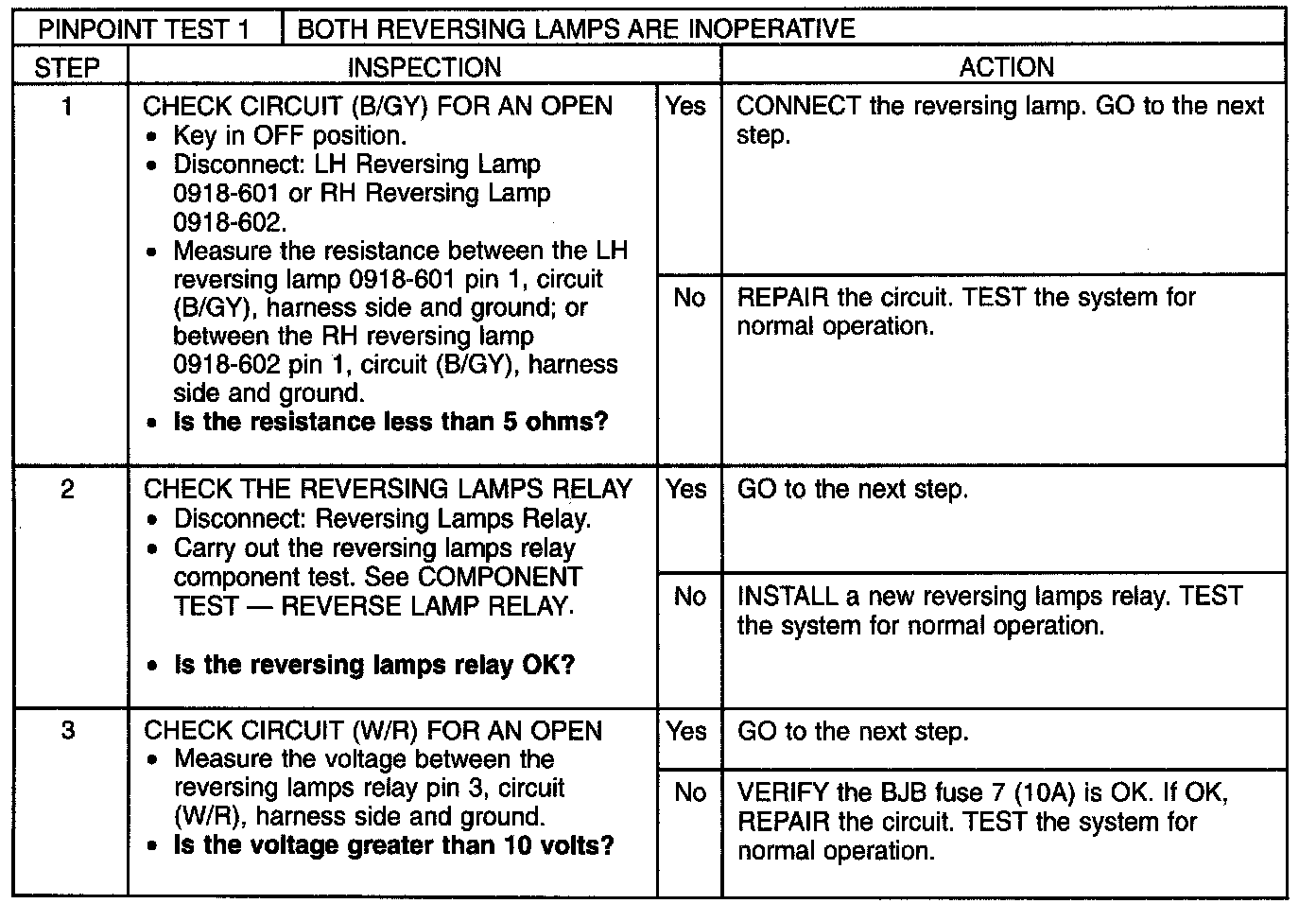
Step 1-Step 3:
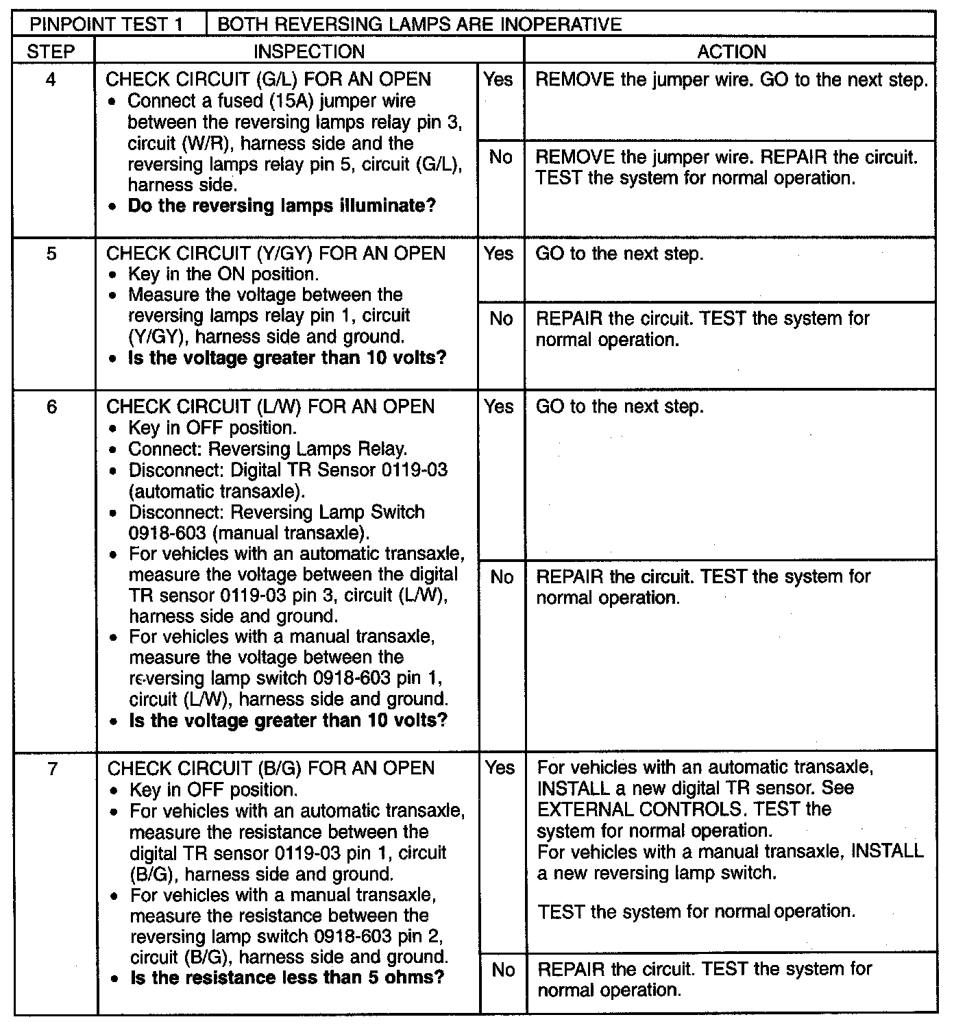
Step 4-Step 7: