Removal and Replacement
CYLINDER HEAD - 2.3L REMOVAL/INSTALLATION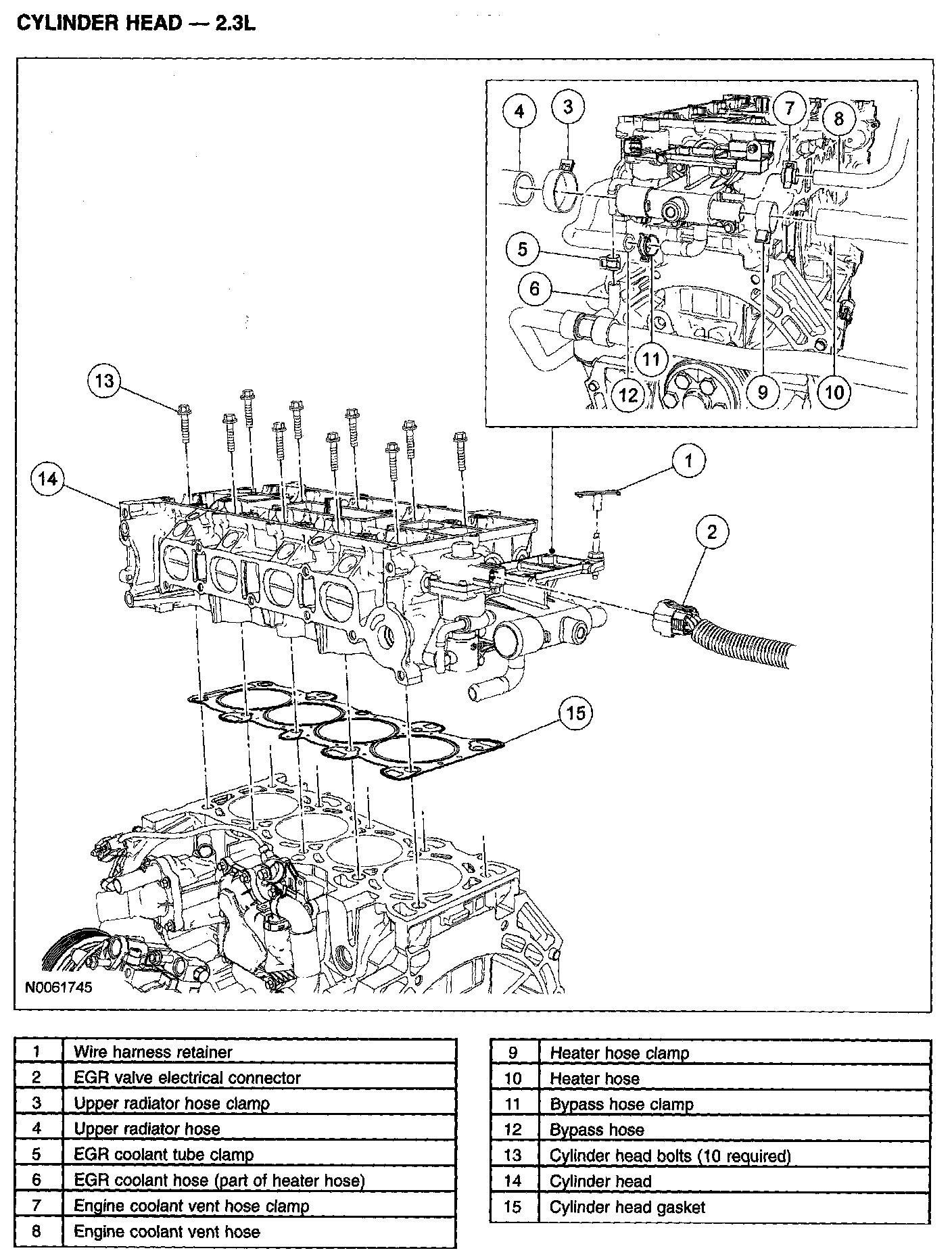
Removal
Caution
^ During engine repair procedures, cleanliness is extremely important. Any foreign material (including any material created while cleaning gasket surfaces) that enters the oil passages, coolant passages or the oil pan can cause engine failure.
Caution
^ Do not loosen or remove the crankshaft pulley bolt without first installing the special tools as instructed in this procedure. The crankshaft pulley and the crankshaft timing sprocket are not keyed to the crankshaft. The crankshaft, the crankshaft sprocket and the pulley are fitted together by friction, using diamond washers between the flange faces on each part. For that reason, the crankshaft sprocket is also unfastened if you loosen the pulley bolt. Before any repair requiring loosening or removal of the crankshaft pulley bolt, the crankshaft and camshafts must be locked in place by the special service tools, otherwise severe engine damage can occur.
1. With the vehicle in NEUTRAL, position it on a hoist.
2. Release the fuel system pressure.
3. Drain the engine coolant.
4. Remove the timing drive components.
5. Remove the special tool.
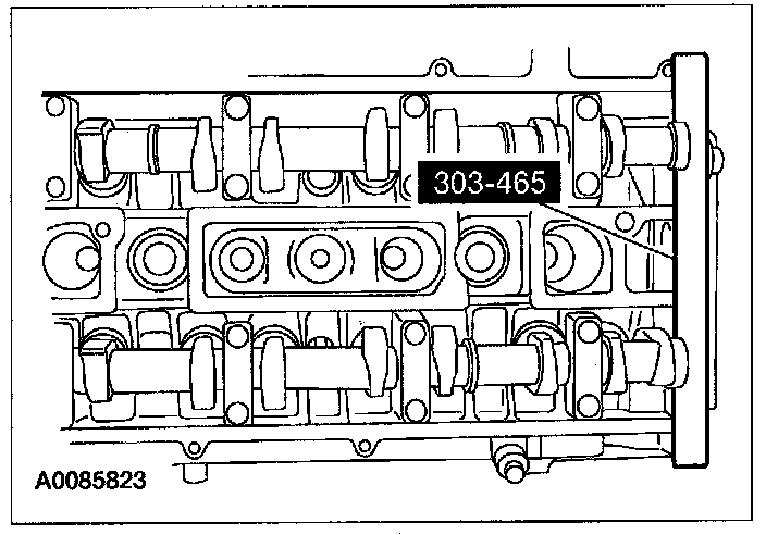
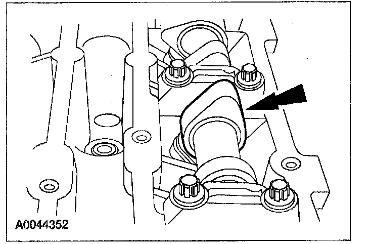
6. Mark the position of the camshaft lobes on the No. 1 cylinder for installation reference.
7. Remove the camshafts from the engine.
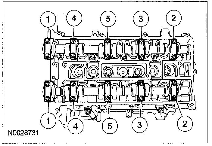
^ Loosen the camshaft bearing cap bolts, in sequence, one turn at a time until all tension is released from the bearing cap bolts.
^ Remove the bolts and the camshaft bearing caps.
^ Remove the camshafts.
Caution
^ Failure to follow the camshaft loosening procedure can result in damage to the camshafts.
Note
^ Mark the location of the camshaft caps to make sure they are assembled in their original positions.
8. Remove the valve tappets.
Note
^ If the camshafts and valve tappets are to be reused, mark the location of the valve tappets to make sure they are assembled in their original positions.
9. Inspect the valve tappets. See VALVE TAPPET INSPECTION - 2.3L. Valve Tappet Inspection
Note
^ The number on the valve tappets only reflects the digits that follow the decimal. For example, a tappet with the number 0.650 has the thickness of 3.650 mm.
10. Remove the intake manifold.
11. Remove the generator.
12. Remove the catalytic converter exhaust manifold.
13. Disconnect the exhaust gas recirculation (EGR) valve electrical connector.
14. Disconnect the EGR coolant hose from the EGR valve.
15. Detach the wire harness retainer from the coolant outlet stud bolt.
16. Disconnect the upper radiator hose, coolant bypass hose, heater hose and coolant vent hose from the engine coolant outlet.
17. Remove the bolts and cylinder head.
^ Discard the bolts and the cylinder head gasket.
Installation
1. Clean the cylinder head-to-cylinder block mating surface of both the cylinder head and the cylinder block.
(1) Remove any large deposits of silicon or gasket material with a plastic scraper.
(2) Apply silicon gasket remover, following package directions, and allow to set for several minutes.
(3) Remove silicone gasket remover with a plastic scraper. A second application of silicon gasket remover may be required if residual traces of silicon or gasket material remain.
(4) Apply metal surface prep, following package directions to remove any traces of oil or coolant, and to prepare the surfaces to bond with the new gasket. Do not attempt to make the metal shiny. Some staining of the metal surfaces is normal.
Caution
^ Do not use metal scrapers, wire brushes, power abrasive discs or other abrasive means to clean the sealing surfaces. These tools cause scratches and gouges that make leak paths. Use a plastic scraping tool to remove all traces of the head gasket.
Note
^ Observe all warnings or cautions and follow all application directions contained on the packaging of the silicone gasket remover and the metal surface prep.
Note
^ If there is no residual gasket material present, metal surface prep can be used to clean and prepare the surfaces.
2. Inspect the cylinder head for distortion. See CYLINDER HEAD DISTORTION CHECK. Cylinder Head Distortion Check
3. Clean the cylinder head bolt holes in the cylinder block. Make sure all coolant, oil or other foreign material is removed.
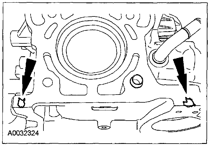
4. Apply silicone gasket and sealant to the locations shown.
5. Install a new head gasket.

6. Install new cylinder head bolts. Tighten the bolts in the sequence shown in 5 stages.
^ Stage 1: Tighten the bolts to 5 N-m (0.5 kgf-m, 44 in-lbf).
^ Stage 2: Tighten the bolts to 15 N-m (1.5 kgf-m, 11 ft-lbf).
^ Stage 3: Tighten the bolts to 45 N-m (4.5 kg-m, 33 ft-lbf).
^ Stage 4: Turn the bolts 90 degrees.
^ Stage 5: Turn the bolts an additional 90 degrees.
Note
^ The cylinder head bolts are torque-to-yield and must not be reused. New cylinder head bolts must be installed.
Note
^ Lubricate the bolts with clean engine oil prior to installation.
7. Connect the upper radiator hose, coolant bypass hose, heater hose and coolant vent hose to the engine coolant outlet.
8. Attach the wire harness retainer to the coolant outlet stud.
9. Connect the EGR coolant hose to the EGR valve.
10. Connect the exhaust gas recirculation (EGR) valve electrical connector.
11. Install the catalytic converter and exhaust manifold.
12. Install the generator.
13. Install the intake manifold.
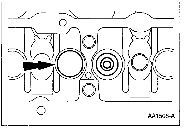
14. Install the valve tappets in their original positions.
Note
^ Lubricate the valve tappets with clean engine oil.
15. Install the camshaft and bearing caps. Tighten the bolts in the sequence shown in 3 stages.
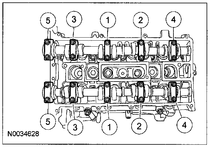
^ Stage 1: Tighten the camshaft bearing cap bolts, one turn at a time, until finger tight.
^ Stage 2: Tighten the bolts to 7 N-m (07 kgf-m, 62 in-lbf).
^ Stage 3: Tighten the bolts to 16 N-m (1.6 kgf-m, 12 ft-lbf).
Caution
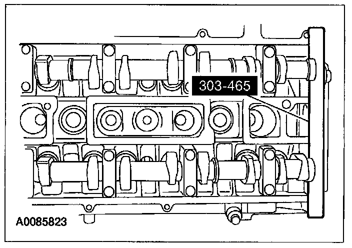
^ Install the camshafts with the alignment notches in the camshafts lined up so the camshaft alignment plate can be installed. Make sure the lobes on the No. 1 cylinder are in the same position as noted in the removal procedure. Failure to follow this procedure can cause severe damage to the valves and pistons.
Note
^ Lubricate the camshaft journals and bearing caps with clean engine oil.
16. Install the special tool.
17. Install the timing drive components.
18. Fill and bleed the engine cooling system.