Removal, M/T
ENGINE - MANUAL TRANSAXLE REMOVALWarning
^ Do not smoke or carry lighted tobacco or open flame of any type when working on or near any fuel-related components. Highly flammable mixtures are always present and may be ignited. Failure to follow these instructions may result in personal injury.
1. With the vehicle in NEUTRAL, position it on a hoist.
2. Release the fuel system pressure.
3. Remove the engine air cleaner and air cleaner outlet pipe.
4. Remove the battery tray.
5. Drain the engine oil.
^ Install the drain plug.
^ To install, tighten to 28 N-m (2.8 kgf-m, 21 ft-lbf).
6. Remove the 2 front wheels and tires.
7. Drain the cooling system.
8. Remove the exhaust flexible pipe.
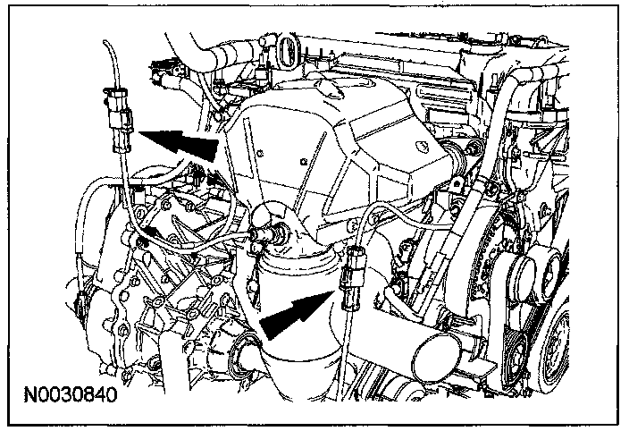
9. Disconnect the heated oxygen sensor (HO2S) and the catalyst monitor sensor electrical connectors.
10. Remove the accessory drive belt and tensioner.
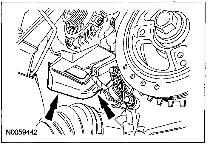
11. Press the 2 locking tabs to release the lower air duct from the upper air duct.
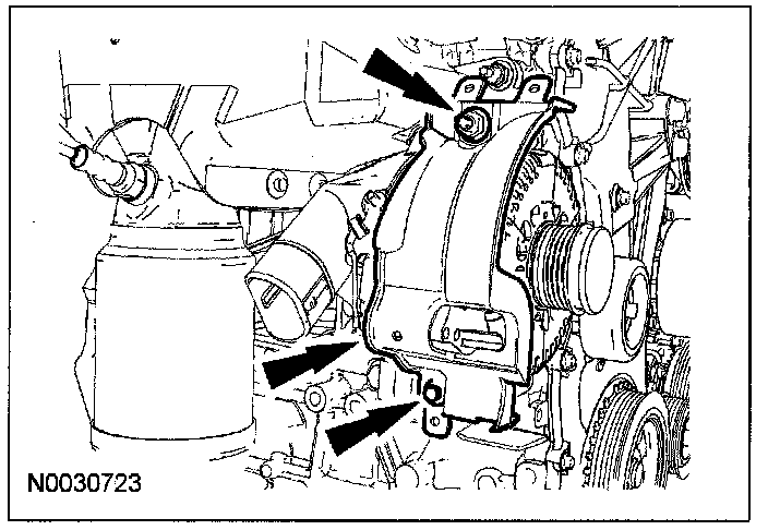
12. Detach the wire retainers from the generator shield and remove the nut and pin-type retainer and remove the generator shield.
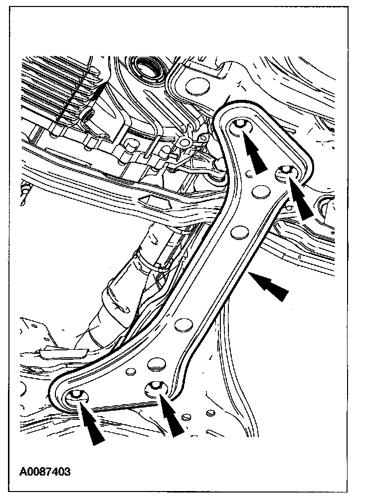
13. Remove the 4 bolts and the lateral support crossmember.
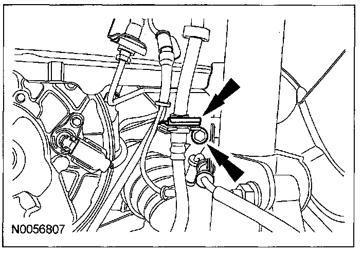
14. Remove the brake hose retainer and the ABS sensor retaining bolt from the LH strut.
15. Disconnect the LH suspension.
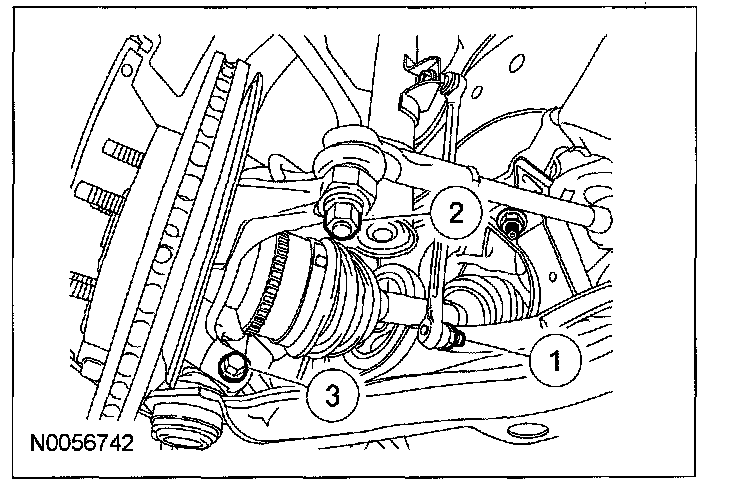
(1) Disconnect the stabilizer bar link.
(2) Remove the tie rod end retaining nut.
(3) Remove the lower control arm knuckle bolt.
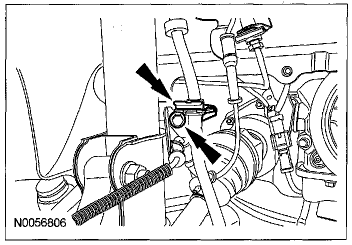
16. Remove the brake hose retainer and the ABS sensor retaining. bolt from the RH strut.
17. Disconnect the RH suspension.
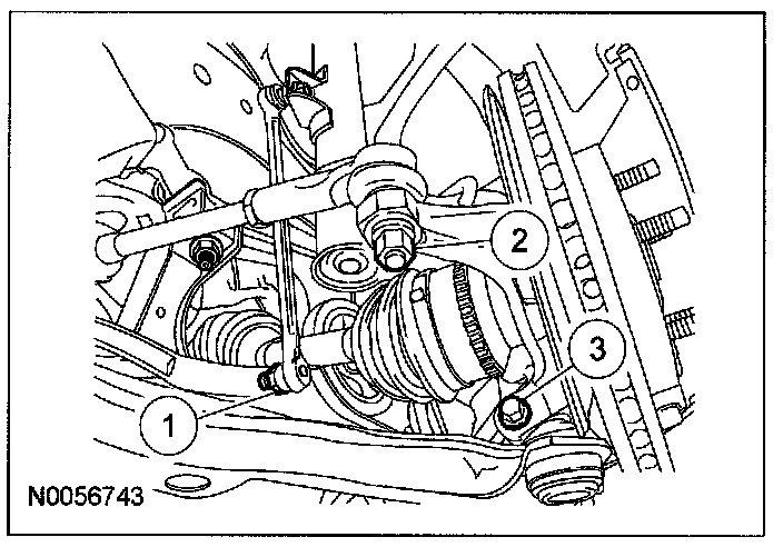
(1) Disconnect the stabilizer bar link.
(2) Remove the tie rod end retaining nut.
(3) Remove the lower control arm knuckle bolt.
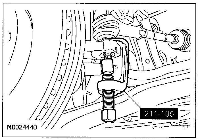
18. Using the special tool, disconnect the LH and RH tie rod end from the steering knuckle.
19. Carefully pry down on the LH and RH lower control arms and disconnect the steering knuckle from the lower ball joint and position the steering knuckle aside.
20. Using a pry bar between the transaxle case and the LH halfshaft, carefully disconnect the halfshaft from the transaxle case and secure the halfshaft aside.
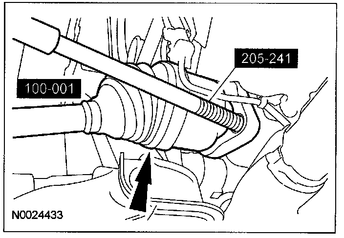
21. Using the special tools, remove the RH halfshaft from the intermediate shaft and secure the halfshaft aside.
22. Remove the 2 intermediate shaft retaining nuts.
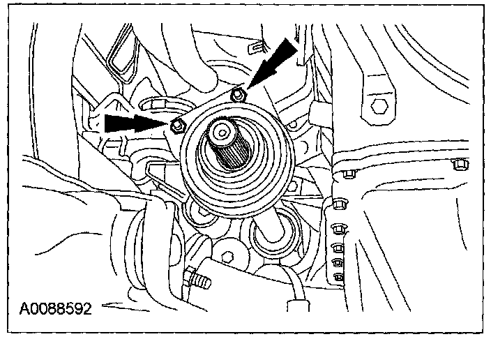
23. Remove the intermediate shaft.
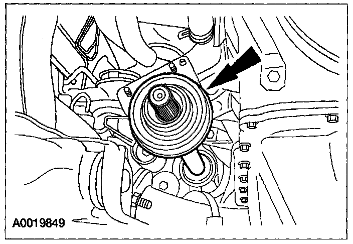
24. Remove the power distribution box (PDB) cover.
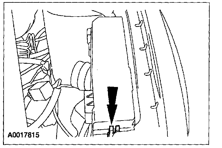
25. Remove the nut and cable from the PDB.
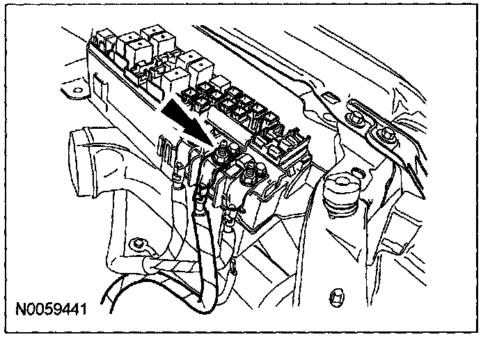
26. Disconnect the electrical connector from the PDB.
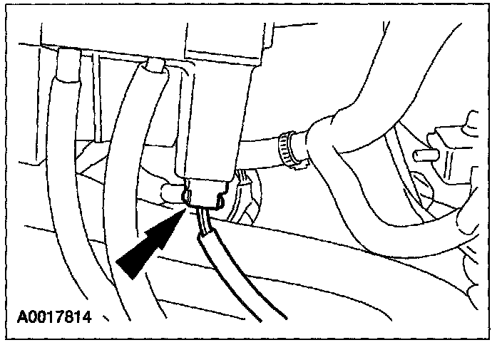
27. Remove the bolt and ground strap.
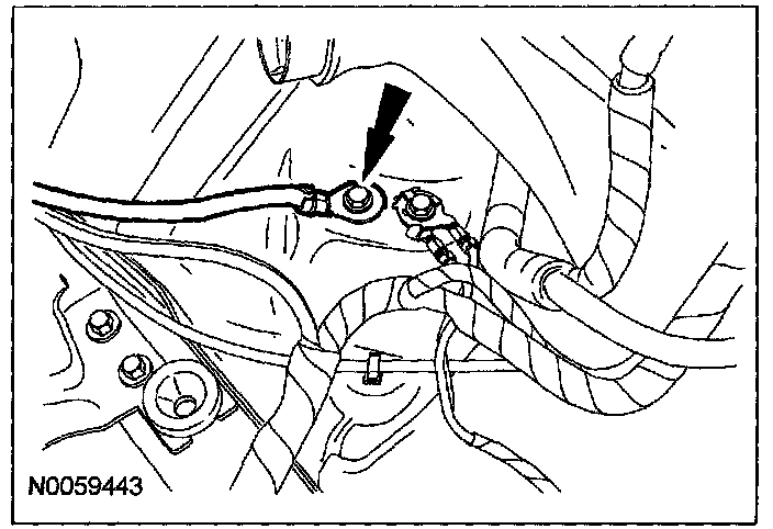
28. Disconnect the 34-pin electrical connector.
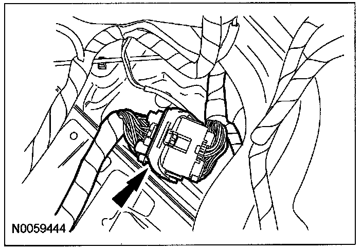
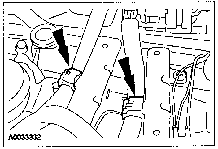
29. Detach the wiring harness retainers from the battery tray bracket and position the wiring harness aside.
30. Position the clutch hydraulic line aside.
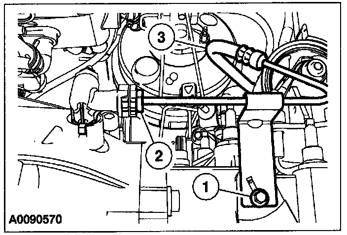
(1) Remove the clutch hydraulic line bracket to transaxle bolt.
(2) Disconnect the clutch hydraulic line from the clutch slave cylinder.
1) Plug the hydraulic line.
(3) Position the clutch hydraulic line aside.
31. Remove the wiring harness bracket nut and position aside.
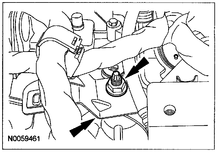
32. Disconnect the vehicle speed sensor (VSS) electrical connector and pin-type retainers.
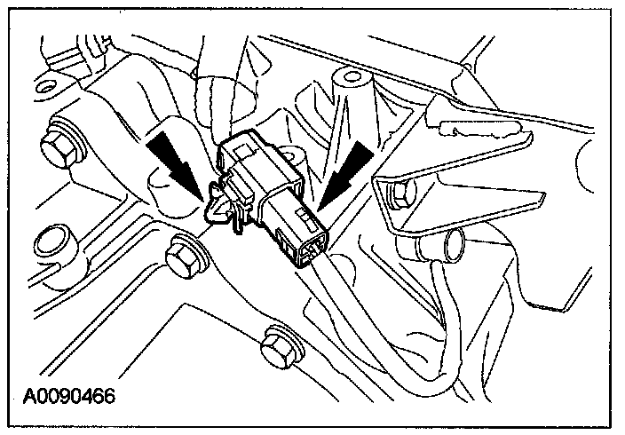
33. Disconnect the reversing lamp indicator switch.
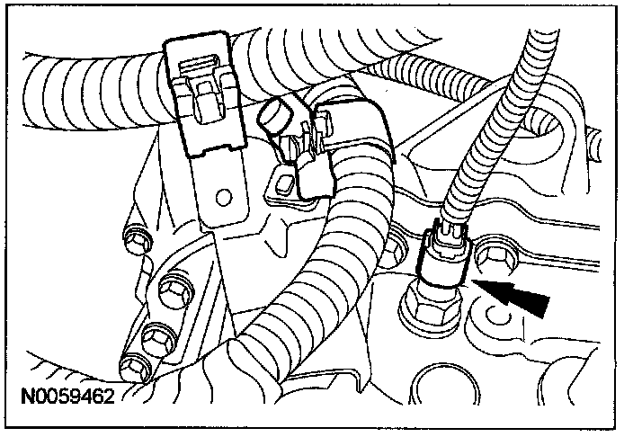
34. Disconnect the shift cables.
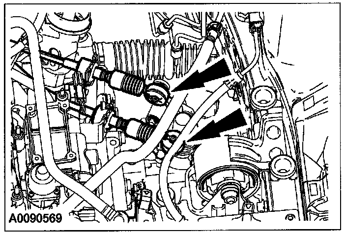
35. Remove the 3 shift cable bracket bolts. Position the bracket aside.
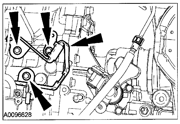
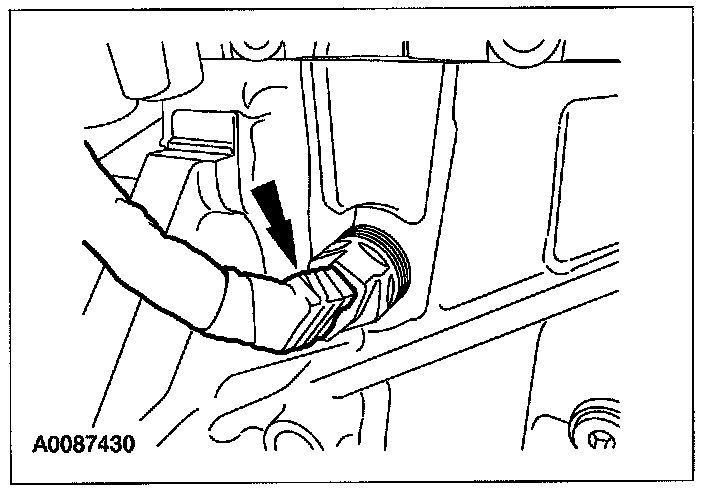
36. If equipped, disconnect the block heater electrical connector. Detach all the block heater wiring harness retainers and position the wiring harness aside.
37. Disconnect the upper radiator hose.
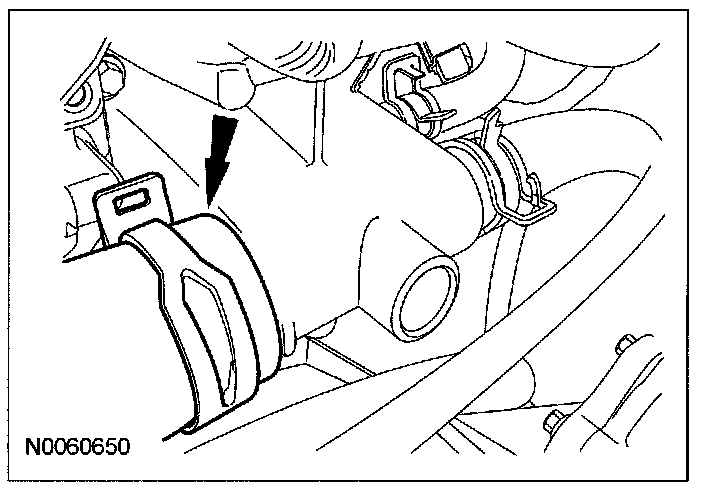
38. Detach the heater hose support strap from the stud.
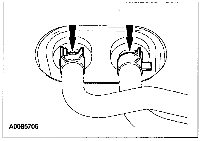
39. Disconnect the heater hoses from the heater core.
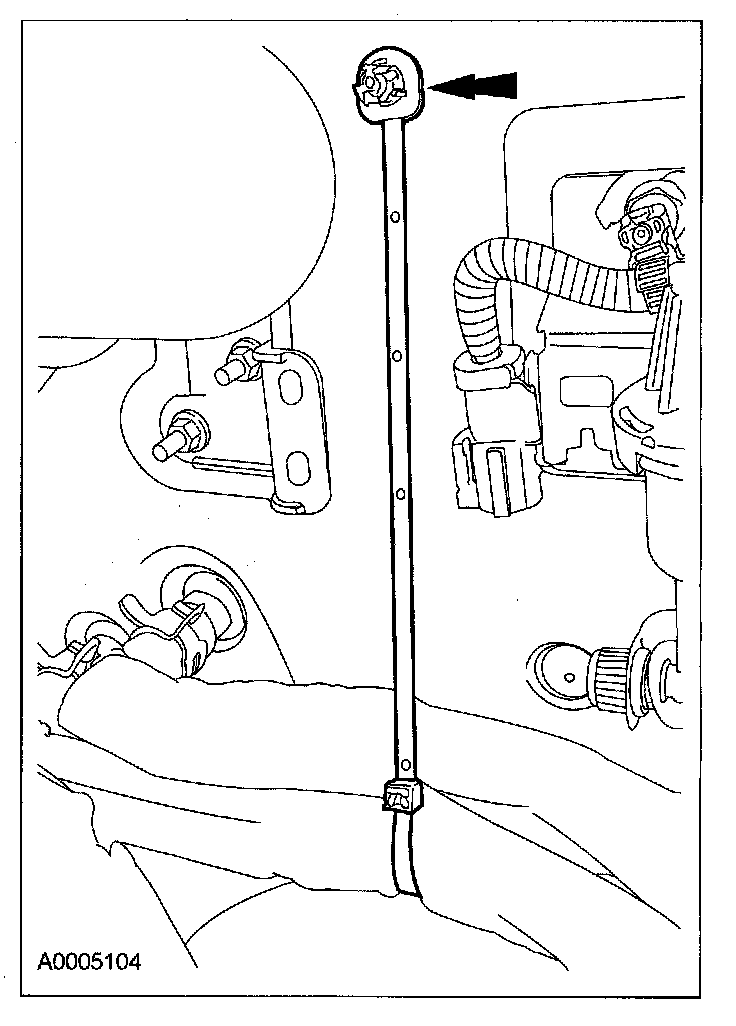
40. Remove the retainers and the accelerator cable snow shield.
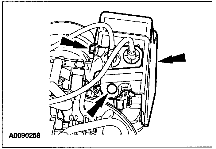
41. Disconnect the accelerator speed control cable (if equipped).
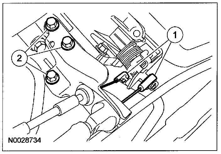
(1) Disconnect the accelerator speed control cable (if equipped) from the throttle body.
(2) Remove the bolts from the accelerator cable bracket.
42. Remove the nut from the accelerator control cable bracket.
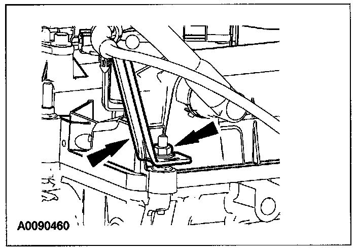
^ Position the accelerator control cable and bracket assembly aside.
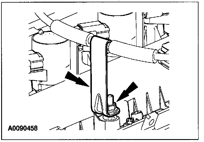
43. Remove the nut from the accelerator control cable bracket.
44. Disconnect the vacuum supply tube and position aside.
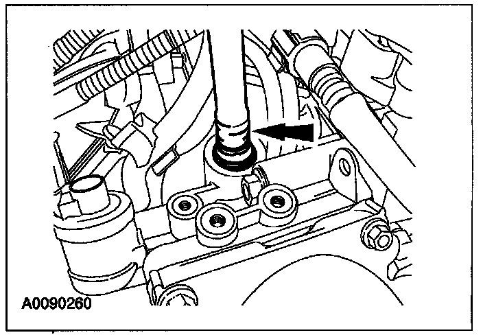
45. Disconnect the fuel vapor tube and position aside.
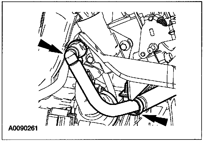
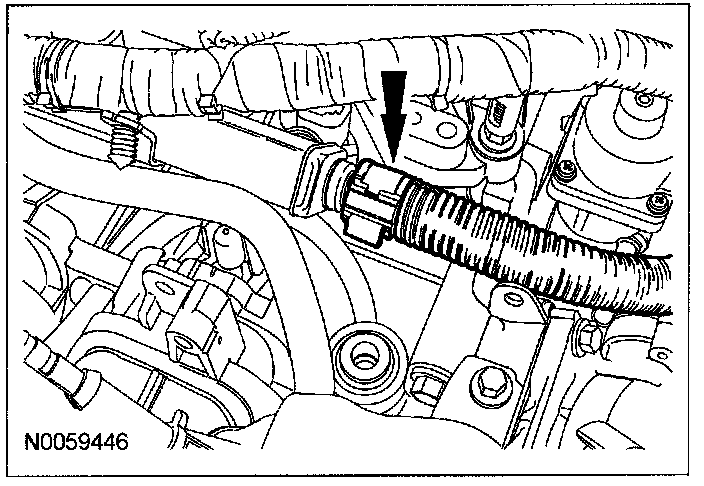
46. Disconnect the fuel supply tube.
47. Detach the electrical connector retainers.
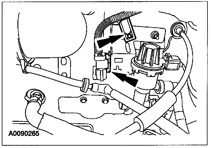
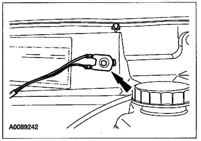
48. Remove the bolt and detach the ground wire.
49. Disconnect the PCM electrical connectors.
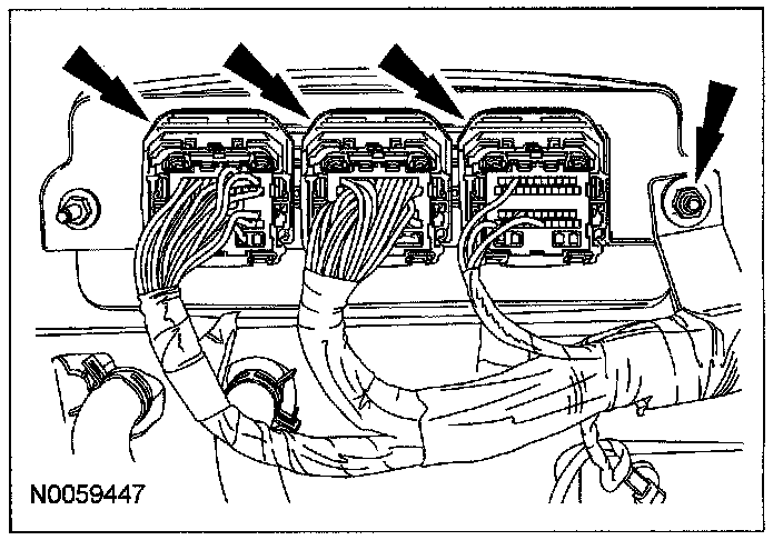
^ Remove the wiring harness retainer nut.
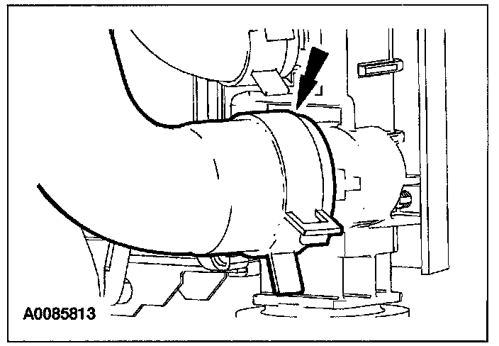
50. Disconnect the lower radiator hose from the radiator.
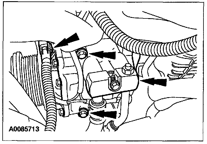
51. Disconnect the A/C compressor electrical connector and remove the 3 bolts.
^ Position the A/C crossmember aside and support the crossmember with a length of mechanic's wire.
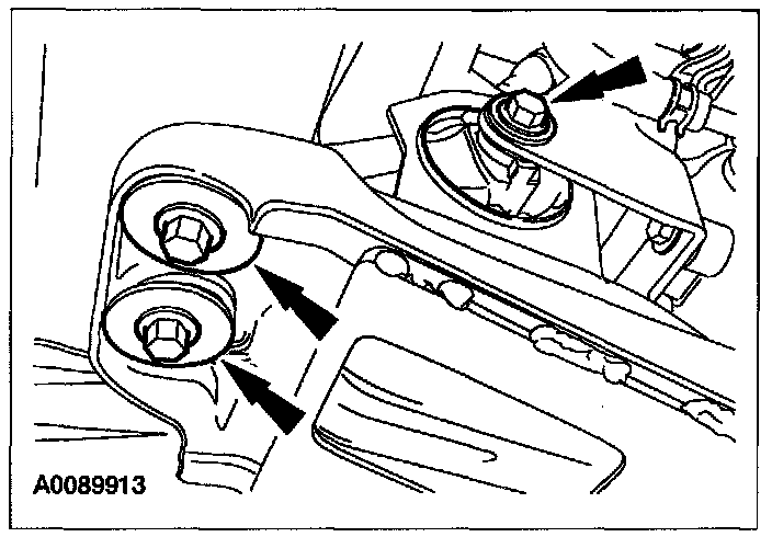
52. Remove the front roll restrictor bolt and the 2 bolts for the engine support crossmember.
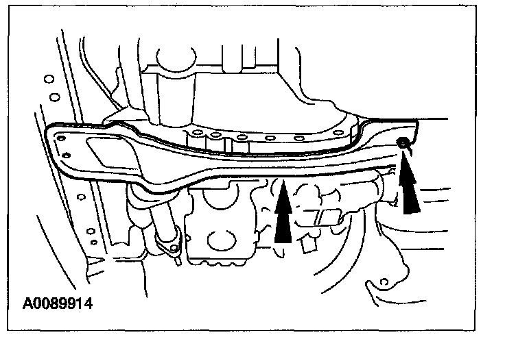
53. Remove the rear nut and the engine support crossmember.
^ Discard the nut.
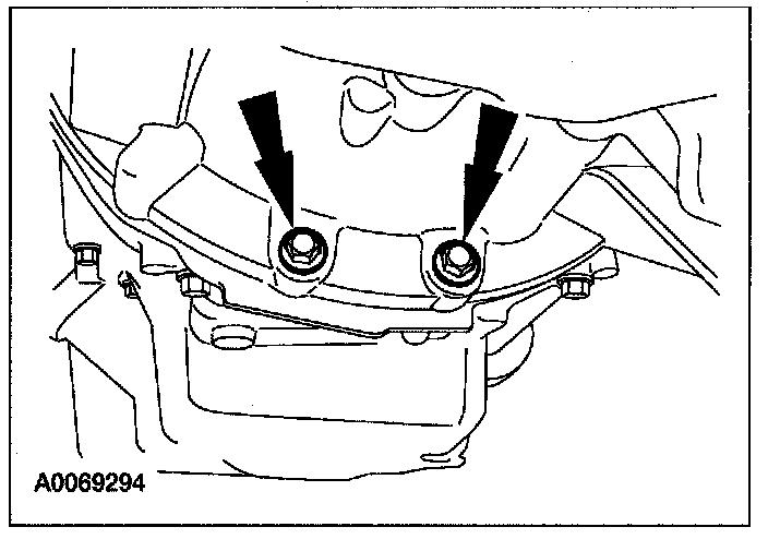
54. Remove the 2 transaxle-to-engine bolts.
Note
^ The transaxle-to-engine bolts differ in length. Mark the bolts for correct installation.
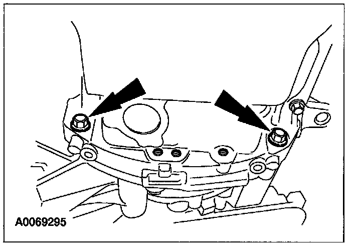
55. Remove the 2 engine-to-transaxle bolts.
Note
^ The transaxle-to-engine bolts differ in length. Mark the bolts for correct installation.
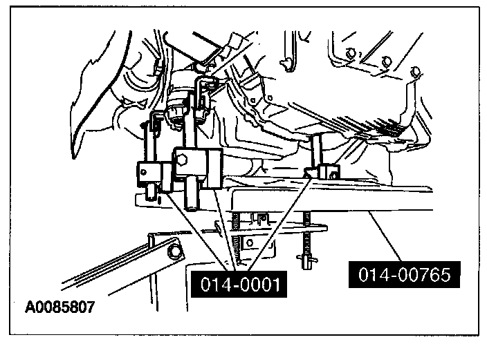
56. Using the special tools, secure the engine to the lift table.
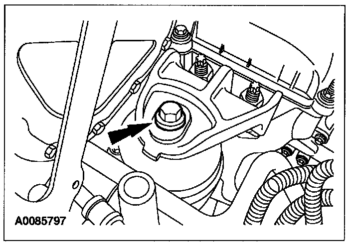
57. Remove the engine mount bracket bolt.
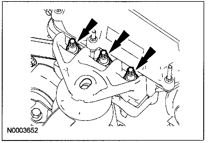
58. Remove the nuts and the engine mount bracket.
59. Remove the bolt from the transaxle rear mount.
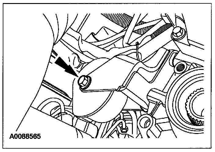
60. Remove bolt from LH transaxle mount.
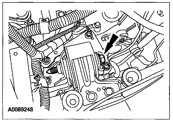
61. Lower the engine and transaxle from the vehicle.
62. Disconnect the starter terminals.
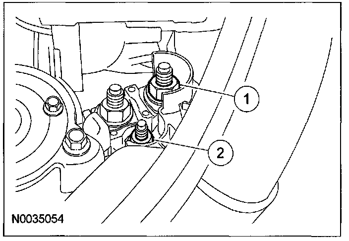
(1) Remove the battery cable nut.
(2) Remove the starter solenoid terminal nut.
63. Remove the wire harness clip retainer and the ground wire from the starter bolts.
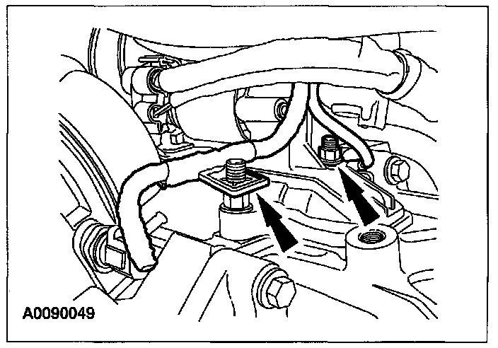
64. Remove the 2 stud bolts and remove the starter.
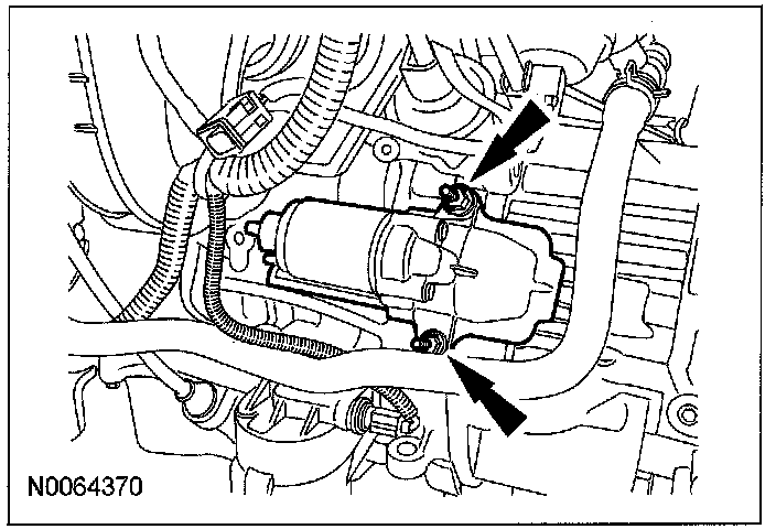
65. Using the engine crane and spreader bar, remove the engine and transaxle from the lift table.
66. Remove the remaining 5 engine-to-transaxle bolts and separate the engine and transaxle.
Note
^ The transaxle-to-engine bolts differ in length. Mark the bolts for correct installation.