Initial Inspection and Diagnostic Overview
ANTI-LOCK BRAKE SYSTEM (ABS) DIAGNOSIS
Inspection and Verification
1. Verify the customer concern.
2. Visually inspect for obvious signs of mechanical and electrical damage.
Visual Inspection Chart
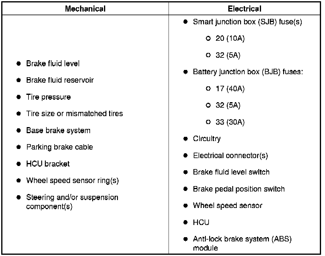
3. If an obvious cause for an observed or reported concern is found, correct the cause (if possible) before proceeding to the next step.
4. If the concern remains after the inspection, connect the Integrated Diagnostic System (IDS) or equivalent tester to the data link connector (DLC) located beneath the instrument panel and select the vehicle to be tested from the IDS or equivalent tester menu. If the IDS or equivalent tester does not communicate with the vehicle:
- check that the program card is correctly installed.
- check the connections to the vehicle.
- check the ignition switch position.
5. If the IDS or equivalent tester still does not communicate with the vehicle, refer to the IDS or equivalent tester manual.
6. Carry out the IDS or equivalent tester data link test. If the IDS or equivalent tester responds with:
- ISO circuit fault; all electronic control units no response/not equipped, see Communications Network.
- No response/not equipped for the ABS module, see Pinpoint Test 1: No Communication With The Anti-Lock Brake System (ABS) Module.
- System passed, retrieve and record the continuous diagnostic trouble codes (DTCs), erase the continuous DTCs. If no DTCs are present, carry out the self-test diagnostics for the ABS control module with the brake pedal not applied.
7. If the DTCs retrieved are related to the concern, see Anti-Lock Brake System (ABS) Module Diagnostic Trouble Code (DTC) Index.
8. If no DTCs related to the concern are retrieved, see - Symptom Related Diagnostic Procedures.