Front Steering Knuckle: Service and Repair
WHEEL KNUCKLE
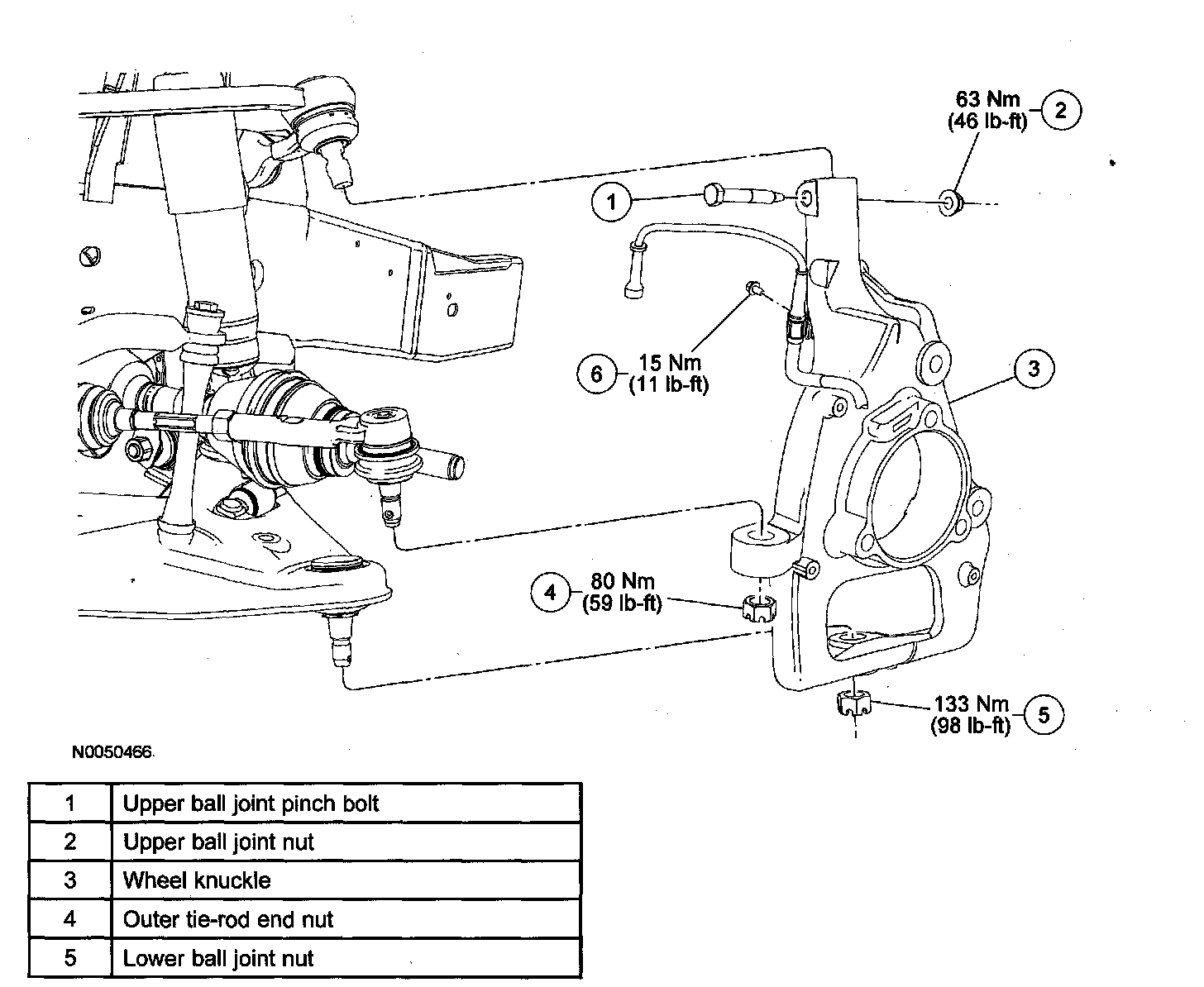
Removal and Installation
CAUTION:Suspension fasteners are critical parts because they affect performance of vital components and systems and their failure may result in major service expense. New parts must be installed with the same part number or an equivalent part if replacement is necessary. Do not use a replacement part of lesser quality or substitute design. Torque values must be used as specified during reassembly to make sure of correct retention of these parts.
1. Remove the wheel bearing and wheel hub assembly. See Service and Repair.
2. Remove the wheel speed sensor harness bolt.Tightening Torque:15 Nm {1.5 kgf-m, 11 ft-lbf}
3. Remove the outer tie-rod end nut.Tightening Torque:80 Nm {8.2 kgf-m, 59 ft-lbf}
- Install a new cotter pin.
1.
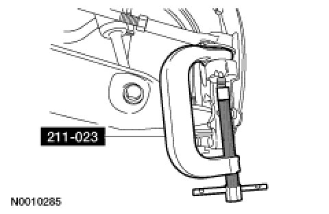
CAUTION:Do not use a hammer to separate the outer tie-rod end from the wheel knuckle or damage to the wheel knuckle will result.
CAUTION:Do not damage the outer tie-rod end boot when installing the special tool.
Using SST 211-023, separate the outer tie-rod end from the front wheel knuckle.
2. Using a suitable jack, support the front suspension lower arm.
3. Remove and discard the lower ball joint cotter pin and nut.Tightening Torque133 N-m {13.6 kgf-m, 98 ft-lbf}
1.
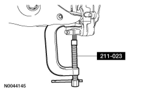
CAUTION:Do not use a hammer to separate the ball joint from the wheel knuckle or damage to wheel knuckle will result.
CAUTION:Do not damage the ball joint boot when installing the special tool. Using SST 211-023, separate the ball joint from the wheel knuckle.
2. Remove the upper ball joint pinch bolt and nut and the wheel knuckle.Tightening Torque63 N-m {6.4 kgf-m, 46 ft-lbf}
3.
CAUTION:Always install the cotter pin into the outer tie-rod end nut from the outboard to inboard, with the fingers bent together at a right angle. Failure to do so will result in damage to the wheel and tire assembly.To install, reverse the removal procedure.
- Check and, if necessary, align the front end. See Wheel Alignment Pre-Inspection.