Part 2
ENGINE - 3.0L (4V) REMOVAL Continued43. Disconnect the evaporative emissions (EVAP) canister purge valve tube from the intake manifold.
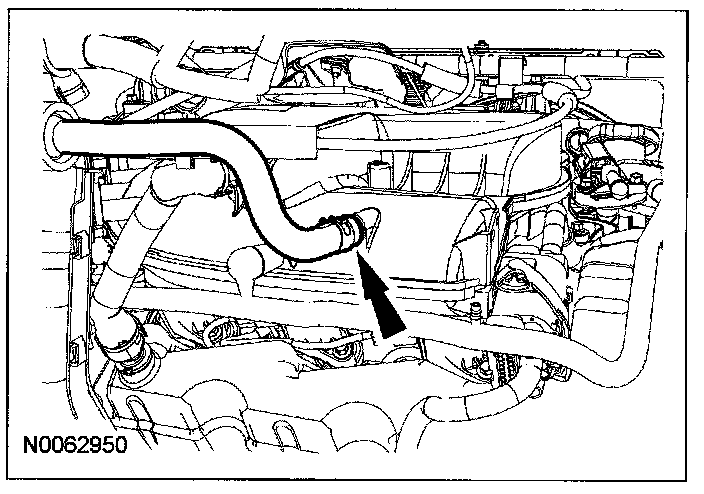
44. Disconnect the brake booster vacuum tube from the intake manifold.
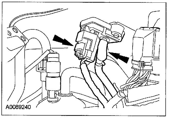
45. Disconnect the manifold absolute pressure (MAP) sensor vacuum tube and electrical connector.
46. Disconnect the PCM electrical connectors and remove the nut.
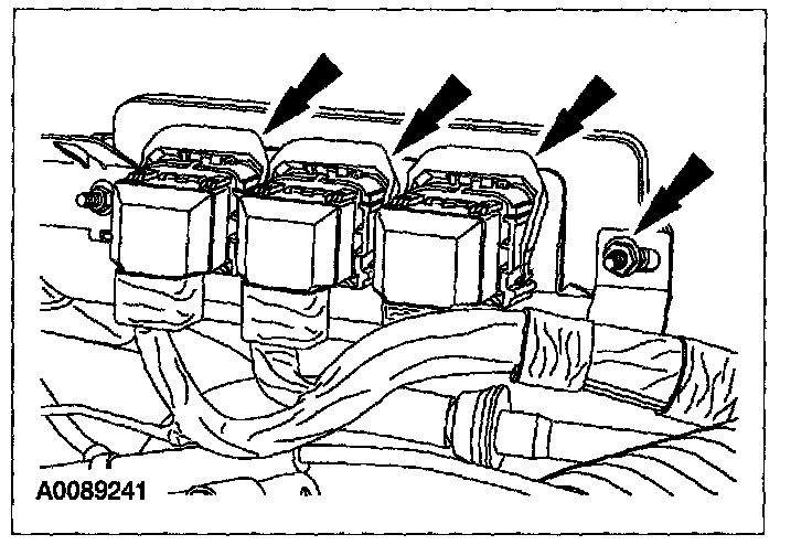
47. Remove the bolt and detach the ground wire.
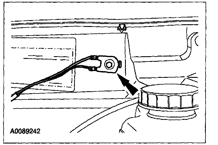
48. Remove the nut and disconnect the cable from the power distribution box.
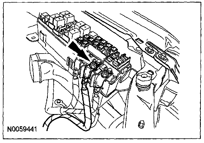
49. Disconnect the electrical connector from the power distribution box.
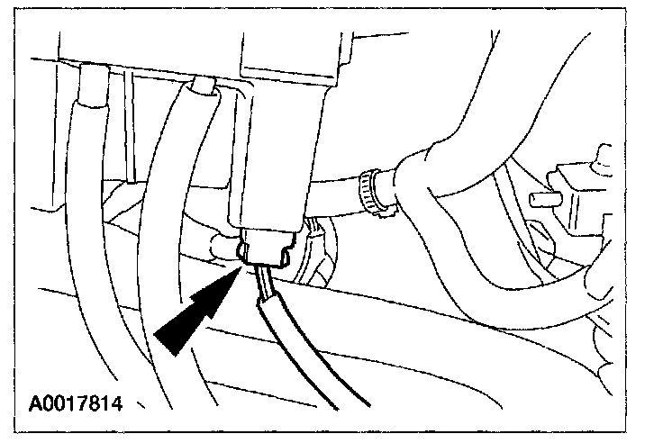
50. Remove the bolt and disconnect the ground wire and the electrical connector.
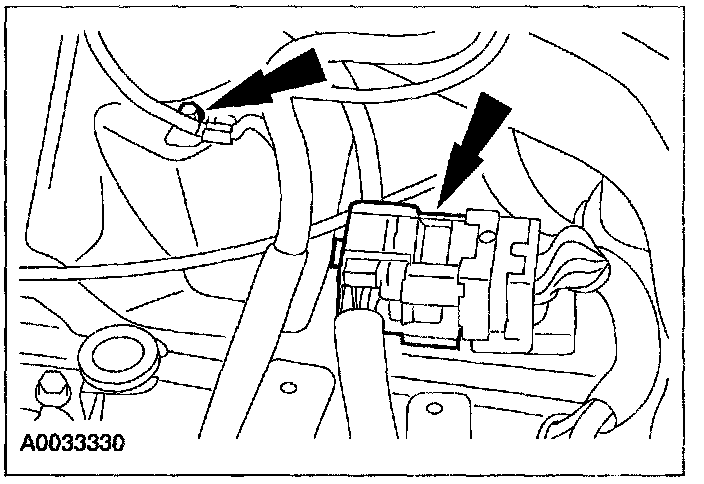
51. Detach the wiring harness retainers from the battery tray bracket.
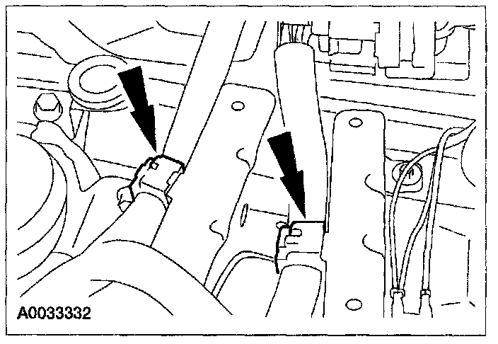
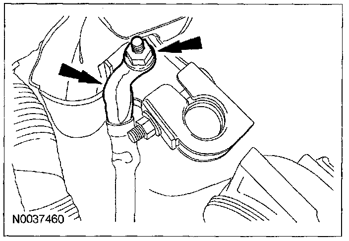
52. Remove the nut and disconnect the wire from the battery cable.
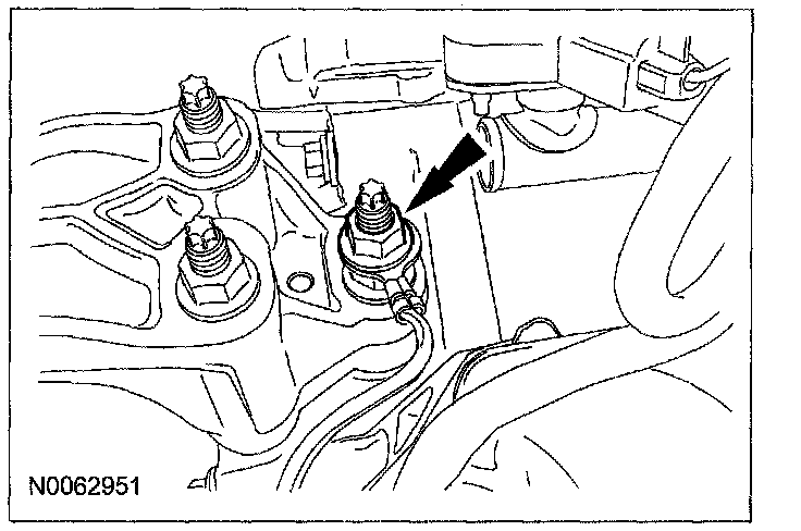
53. Remove the nut and the ground wire from the engine mount stud.
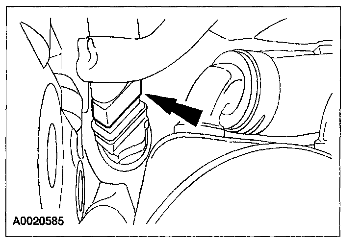
54. If equipped, disconnect the engine block heater electrical connector.
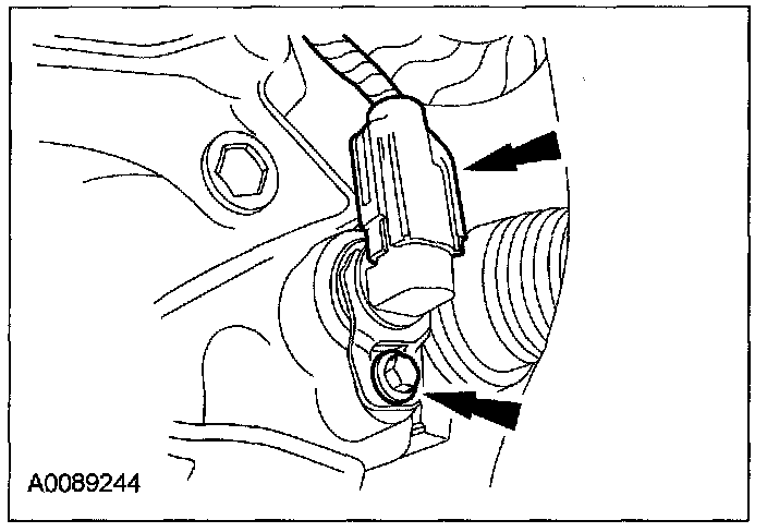
55. Disconnect the output shaft speed (OSS) sensor electrical connector and remove the bolt and the OSS sensor.
56. Remove the torque converter inspection cover.
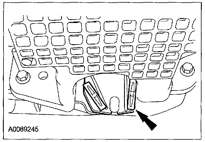
57. Remove the 4 torque converter nuts.
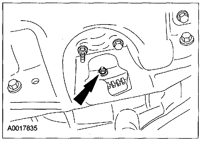
58. Remove the 2 oil pan-to-transaxle bolts.
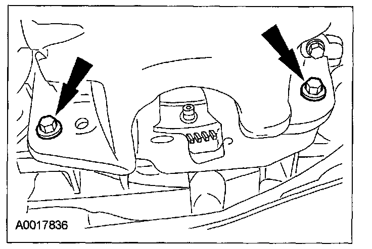
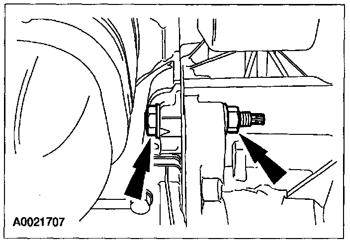
59. Remove the 2 nuts and transaxle-to-engine stud.
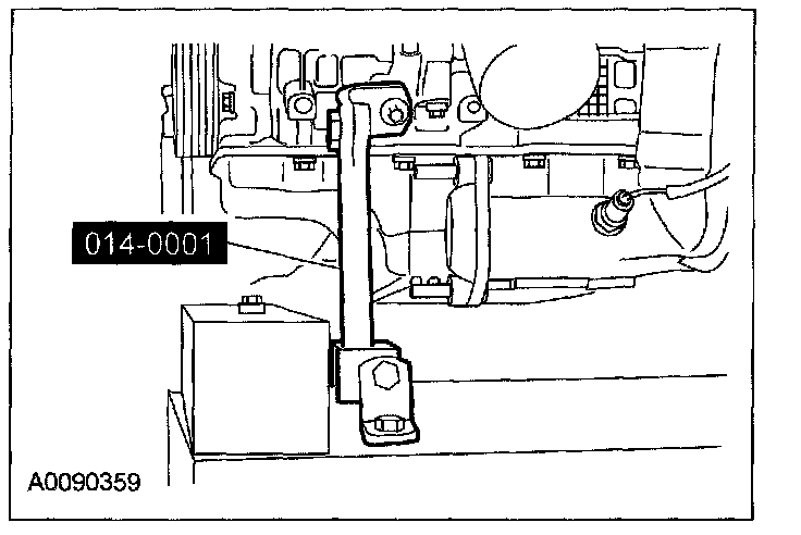
60. Using the special tools, secure the engine and transaxle to the powertrain lift.
Caution
^ Do not allow the engine oil pan to rest on the powertrain lift. Doing so may cause damage to the oil pan.
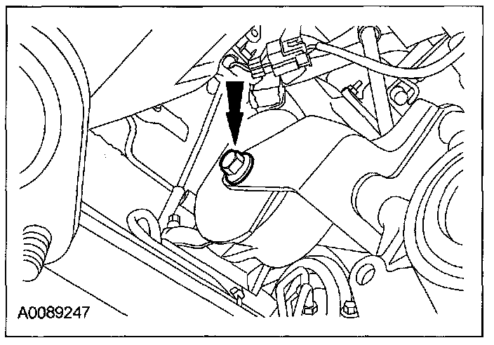
61. Remove the RH transaxle support insulator bolt.
Note
^ The next 5 steps must be carried out with the vehicle raised and the powertrain lift in position.
62. Remove the bolts, nuts and the RH transaxle support insulator.
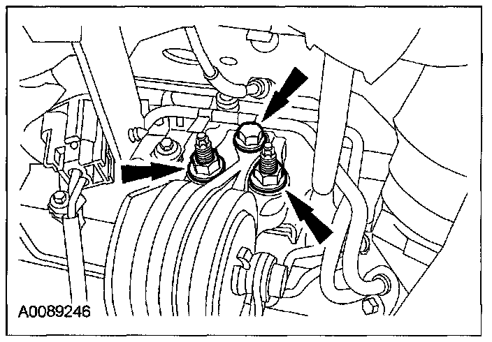
63. Remove the rear transaxle support bolt.
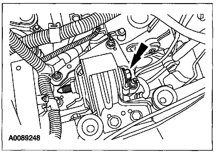
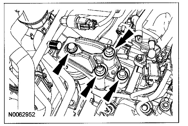
64. Remove the 3 engine support bracket nuts and the bolt.
^ Remove the engine support bracket.
65. Lower the powertrain from the vehicle.
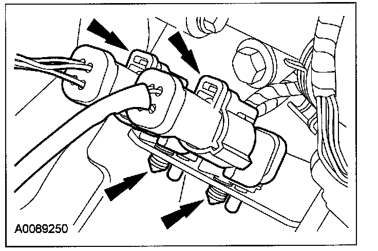
66. Disconnect the LH heated exhaust gas oxygen (HEGO) sensor and LH catalyst monitor sensor electrical connectors.
^ Detach the 3 pin-type retainers from the transaxle support bracket.
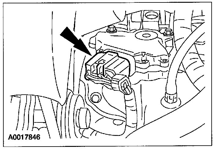
67. Disconnect the transmission range (TR) sensor electrical connector.
68. Disconnect the transaxle electronic control switch electrical connector.
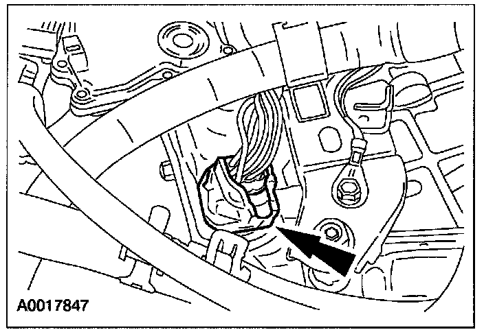
69. Detach the wiring harness from the bracket.
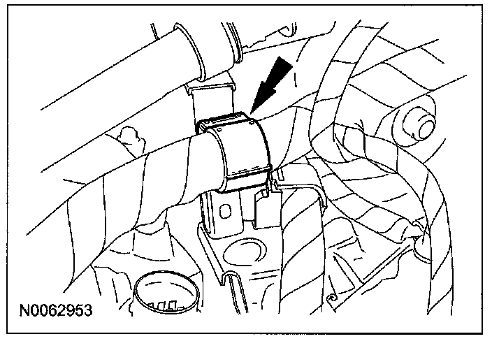
70. Disconnect the turbine speed sensor (TSS) electrical connector.
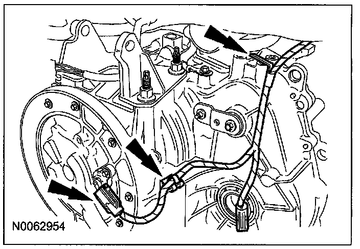
^ Detach the 2 wiring harness retainers.
AWD Vehicles
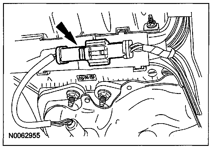
71. Disconnect the RH H02S electrical connector.
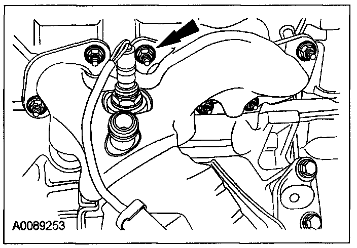
72. Remove the 6 RH exhaust manifold nuts and the manifold.
^ Discard the nuts and gasket.
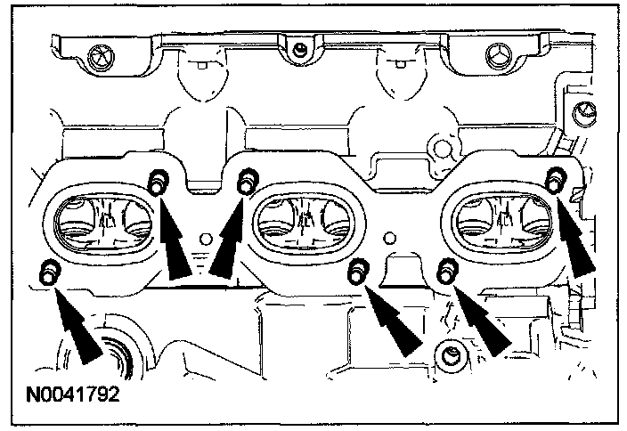
73. Remove and discard the 6 RH exhaust manifold studs.
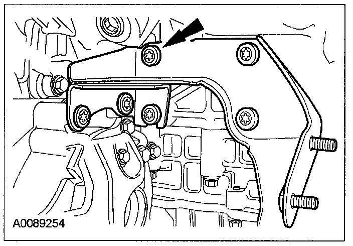
74. Remove the 6 bolts and the halfshaft support bracket.
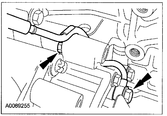
75. Remove the bolt, detach the pin-type retainer and position the power transfer unit (PTU) vent tube aside.
76. Remove the 3 PTU bolts.
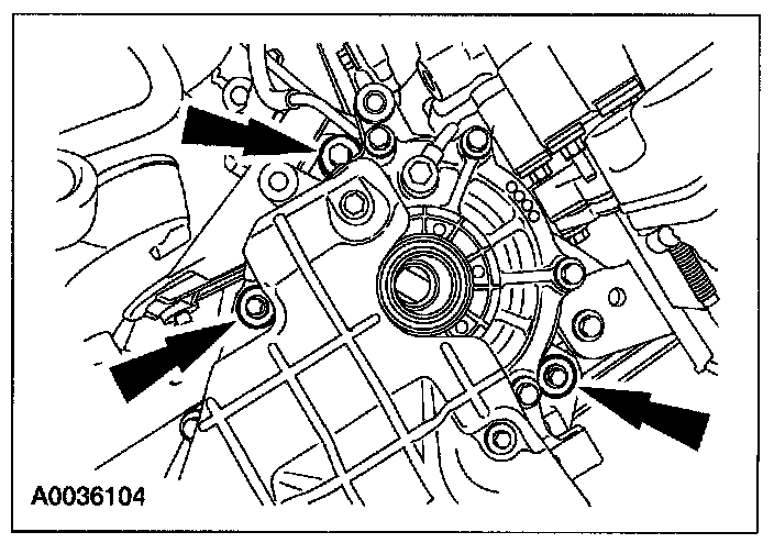
77. Remove the bolt and the PTU.
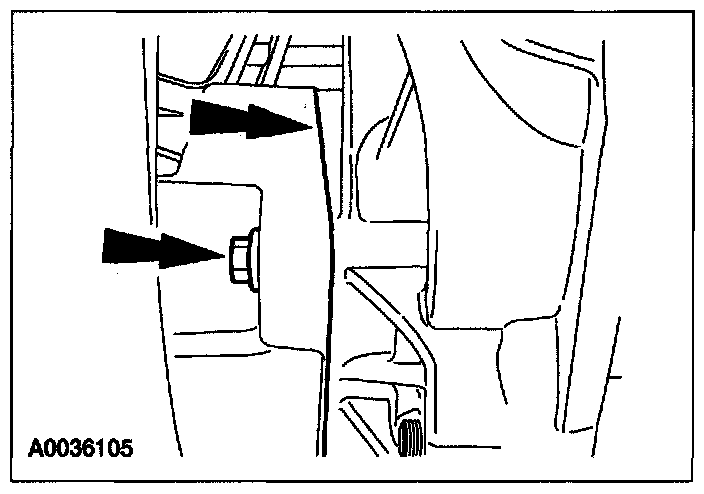
All Vehicles
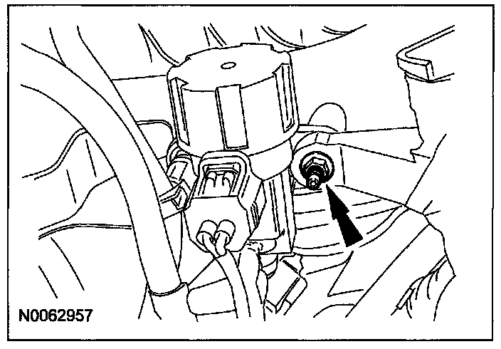
78. Remove the nut and detach the wiring harness retainer.
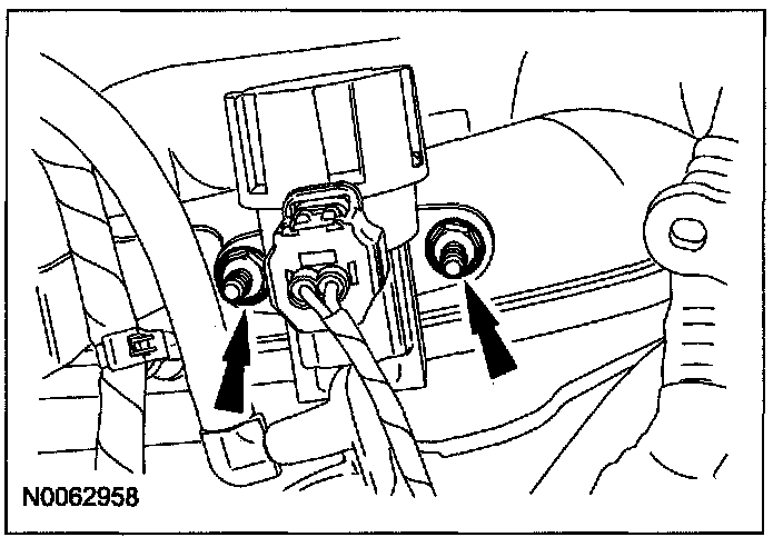
79. Remove the 2 stud bolts and position the EGR regulator aside.
80. Install the lower half of the special tool.

Note
^ When installing the lower half of the lifting bracket it will be easier to loosely install the upper bolt first then install the lower bolt.
81. Install the upper half of the special tool.
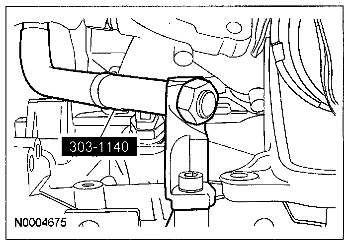
82. Install the special tools in front of the RH cylinder head.
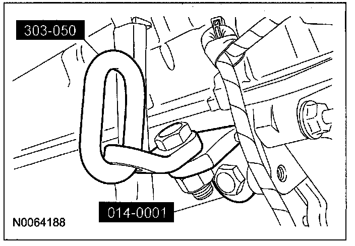
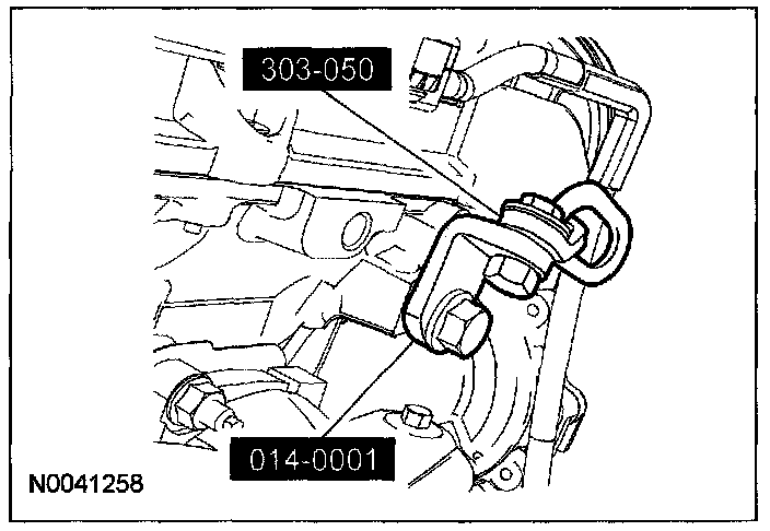
83. Install the special tools to the rear of the LH cylinder head.
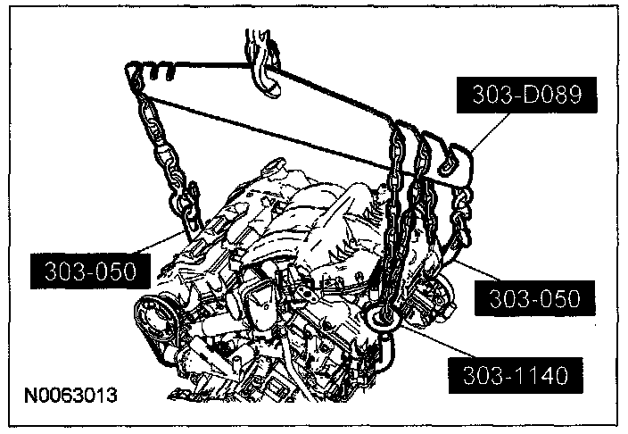
84. Using the special tools and a suitable engine crane, remove the engine and transaxle from the lift table.
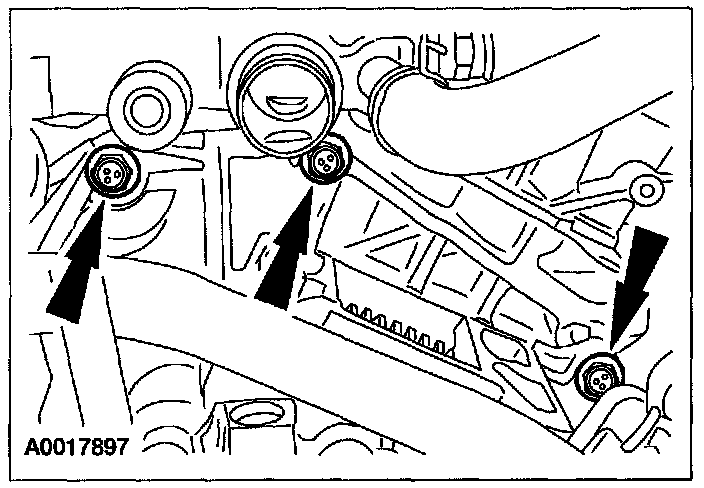
85. Remove the 5 remaining transaxle-to-engine bolts (3 shown).
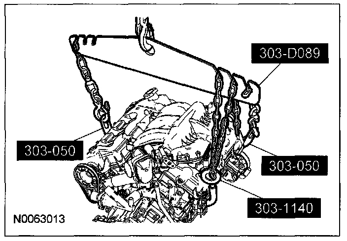
86. Using the special tools and a suitable engine crane, separate the engine and transaxle.