Output Yoke/Flange: Service and Repair
OUTPUT FLANGE REMOVAL/INSTALLATION
Removal
NOTE:This procedure applies to vehicles equipped with automatic transaxles.
1. Remove the driveshaft. See Removal and Replacement.
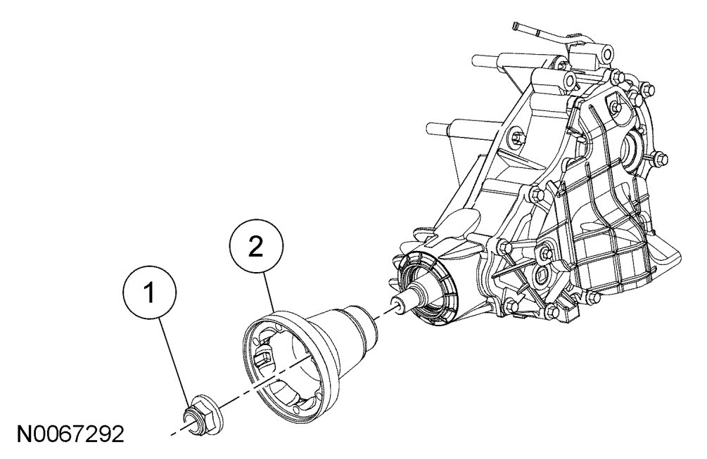
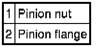
2. Using the Drive Pinion Flange Holding Fixture to hold the flange, remove the pinion nut.
CAUTION:Rotational torque of the power transfer unit (PTU) rear output shaft flange must be measured and recorded using a Nm {kgf-m, in-lbf} torque wrench for correct pinion bearing preload when reassembled.
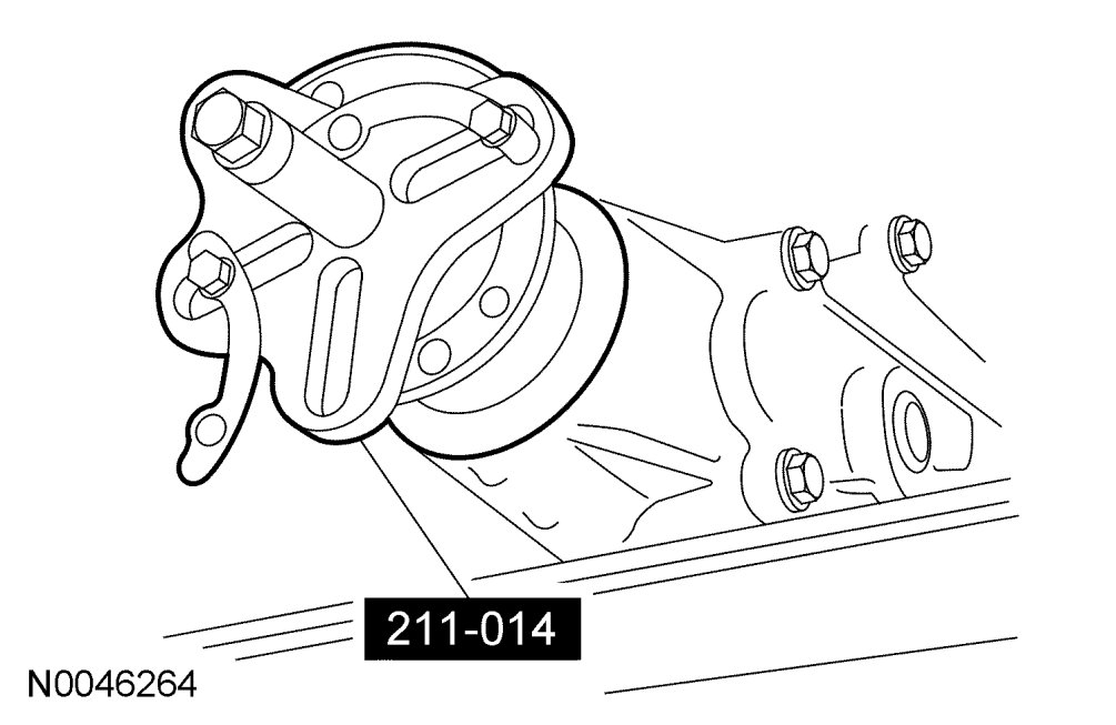
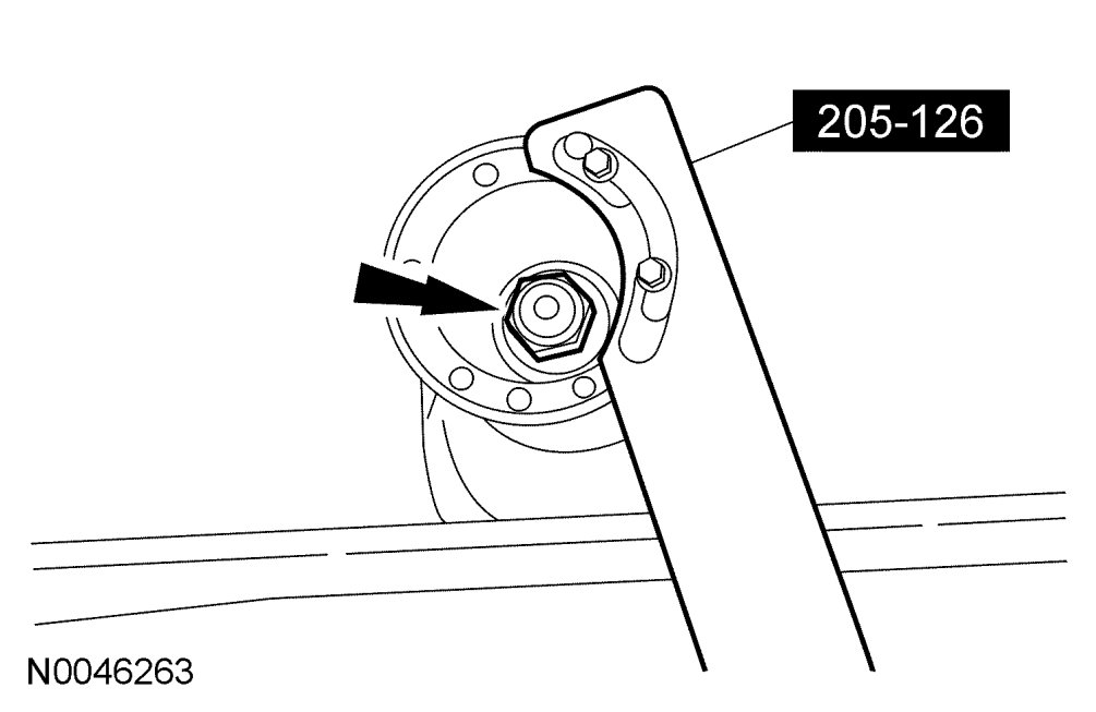
3. Using the Steering Wheel Remover, remove the PTU rear output shaft flange.
NOTE:Index-mark the PTU rear output shaft flange relative to the pinion spline.
Installation
1. Install the PTU rear output shaft flange to engage the spline as previously marked. Install the PTU rear output shaft flange.
2. Using the Drive Pinion Flange Holding Fixture, install the pinion nut.
CAUTION:Do not overtighten the pinion nut. Refer to the rotational torque previously recorded with a Nm {kgf-m, in-lbf} torque wrench. Overtightening the pinion nut will damage the collapsible spacer.
CAUTION:If the rotational torque is less than specification, tighten the drive pinion nut in small increments until it is within specification. Do not tighten the drive pinion nut more than 3 Nm {0.3 kgf-m, 27 in-lbf} at a time or the collapsible spacer will be damaged. If the rotation torque is higher than specification, the collapsible spacer has been compressed too far and a new collapsible spacer must be installed.
3. Install the driveshaft. See Removal and Replacement.