 |
absggw00000342
CYLINDER HEAD GASKET REPLACEMENT [WLT-1, WLT-2]
id011096800700
1. Disconnect the negative battery cable.
2. Drain the engine coolant. (See COOLING SYSTEM SERVICE WARNINGS [WLT-1, WLT-2, WL-3].)
3. Remove the intake manifold, air intake pipe and breather chamber. (See INTAKE-AIR SYSTEM REMOVAL/INSTALLATION [WLT-1, WLT-2].)
4. Remove the injection nozzle. (See INJECTION NOZZLE REMOVAL/INSTALLATION [WLT-1, WLT-2].)
5. Remove the turbocharger. (See EXHAUST SYSTEM REMOVAL/INSTALLATION [WLT-1, WLT-2].)
6. Remove the timing belt. (See TIMING BELT REMOVAL/INSTALLATION [WLT-1, WLT-2].)
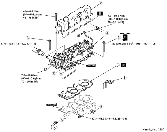
7. Remove in the order indicated in the table.
8. Install in the reverse order of removal.
9. Adjust the drive belt deflection. (See DRIVE BELT ADJUSTMENT [WLT-1, WLT-2].)
10. Bleed air in the fuel line. (See AFTER REPAIR PROCEDURE [WLT-1, WLT-2].)
11. Start the engine and
12. Inspect the compression.
absggw00000342
|
|
1
|
Drive belt
|
|
2
|
Cylinder head cover
|
|
3
|
Cylinder head bolt
|
|
4
|
Cylinder head
|
|
5
|
Cylinder head gasket
|
Cylinder Head Bolt Removal Note
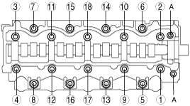
1. Remove bolts A.
2. Loosen the cylinder head bolts in two or three steps in the order shown.
absggw00000343
|
Cylinder Head Gasket Installation Note
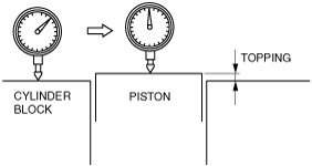
1. Measure the piston topping of all the cylinders.
absggw00000344
|
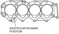
2. Choose the gasket according to each measured piston topping.
absggw00000345
|
Cylinder head gasket select table
|
Piston topping (mm {in}) |
Cylinder head gasket identification mark |
|---|---|
|
0.205—0.325 {0.081—0.127}
|
 |
|
0.265—0.385 {0.105—0.151}
|
 |
|
0.325—0.445 {0.128—0.175}
|
 |
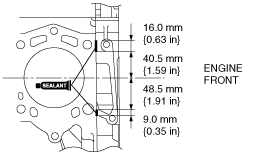
3. Apply silicone sealant to the cylinder block as shown in the figure.
absggw00000349
|
Cylinder Head Bolt Installation Note
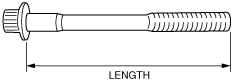
1. Measure the length of each bolt.
absggw00000350
|
2. Apply clean engine oil to the threads and the seat face of each bolt and install them.
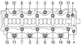
3. Tighten the cylinder head bolts in the order indicated in the figure in several passes.
absggw00000351
|
4. Retighten the bolts in the order shown in the figure until all the bolts are tightened to 29 N·m {3.0 kgf·m, 2.1 ft·lbf}.
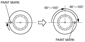
5. Put a paint mark on each bolt head.
6. Using the marks as a reference, tighten the cylinder head bolts by turning each 90°—105° in the order indicated in Step 3.
7. Further tighten each bolt by turning another 90°—105° in the order indicated in Step 3.
absggw00000352
|
8. Tighten bolts A.
Cylinder Head Cover Installation Note
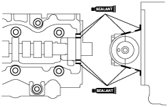
1. Apply silicone sealant to the cylinder head as shown.
absggw00000353
|
2. Tighten cylinder head cover bolts A and B.
absggw00000354
|
3. Tighten the cylinder head cover bolts in the order shown.