 |
absggw00000318
ACCELERATOR PEDAL COMPONENT REMOVAL/INSTALLATION [G6]
id011395807300
1. Disconnect the negative battery cable. (R.H.D.)
2. Set the power brake unit slightly out of the way. (R.H.D.) (See POWER BRAKE UNIT REMOVAL/INSTALLATION.)
3. Set the clutch master cylinder slightly out of the way. (R.H.D.) (See CLUTCH MASTER CYLINDER REMOVAL/INSTALLATION.)
4. Remove the column cover and steering shaft. (R.H.D.) (See STEERING WHEEL AND COLUMN REMOVAL/INSTALLATION.)
5. Remove in the order indicated in the table.
6. Install in the reverse order of removal.
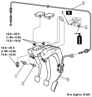
R.H.D.
absggw00000318
|
|
1
|
Neutral switch connector
|
|
2
|
Brake switch connector
|
|
3
|
Accelerator cable
|
|
4
|
Spring pin
|
|
5
|
Clevis pin
|
|
6
|
Pedal component
|
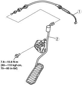
L.H.D.
absggw00000251
|
|
1
|
Accelerator cable
|
|
2
|
Accelerator pedal
|
Pedal Component Installation Note
1. Carry out the “BRAKE PEDAL INSPECTION” procedure after installing the pedal component. (See BRAKE PEDAL INSPECTION.)
2. Carry out the “CLUTCH PEDAL ADJUSTMENT” procedure after installing the pedal component. (See CLUTCH PEDAL ADJUSTMENT.)
Accelerator Cable Installation Note
1. Carry out the “ACCELERATOR CABLE INSPECTION/ADJUSTMENT” procedure after installing the accelerator cable. (See ACCELERATOR CABLE INSPECTION/ADJUSTMENT [G6].)