 |
absggw00001452
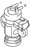
VARIABLE BOOST CONTROL (VBC) SOLENOID VALVE INSPECTION [WL-C, WE-C]
id0113b6804600
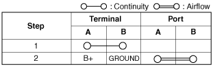
Airflow Inspection
1. Disconnect the negative battery cable.
2. Remove the VBC solenoid valve. (See INTAKE-AIR SYSTEM REMOVAL/INSTALLATION [WL-C, WE-C].)
3. Inspect airflow between the ports under the following conditions.
absggw00001452
|
absggw00001453
|
Resistance Inspection
1. Disconnect the negative battery cable.
2. Disconnect the VBC solenoid valve connector. (See INTAKE-AIR SYSTEM REMOVAL/INSTALLATION [WL-C, WE-C].)
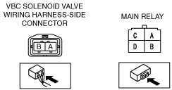
3. Measure the resistance between the VBC solenoid valve terminals using an ohmmeter.
absggw00001454
|
Circuit Open/Short Inspection
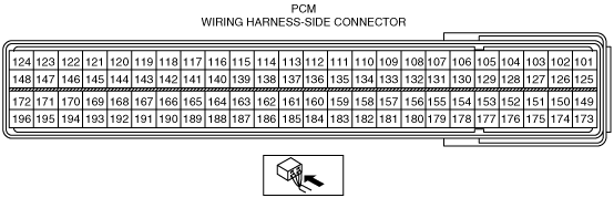
1. Disconnect the PCM connector. (See PCM REMOVAL/INSTALLATION [WL-C, WE-C].) (See PCM REMOVAL/INSTALLATION (U.K. Specs.) [WL-C, WE-C].)
2. Inspect the following wiring harness for open or short circuit (continuity Inspection).
absggw00001455
|
absggw00001456
|
Open circuit
Short circuit