 |
absggw00001278
PCM REMOVAL/INSTALLATION (U.K. Specs.) [WL-C, WE-C]
id0140b7810400
|
STEP |
ACTION |
PAGE/CONDITION |
|---|---|---|
|
1
|
Perform PCM configuration procedure.
|
|
|
2
|
Perform IMMOBILIZER SYSTEM programming.
|
|
|
3
|
Perform PCM data reset procedure.
|
(See PCM DATA RESET [WL-C, WE-C].)
|
|
4
|
Perform After repair procedure.
|
|
|
5
|
Start the engine.
|
–
|
|
6
|
Turn the engine switch to the off position.
|
–
|
|
7
|
Turn the engine switch to the ON position (Engine off).
|
–
|
|
8
|
Perform KOEO self-test procedure.
|
|
|
9
|
Turn the engine switch to the off position.
|
–
|
|
10
|
Wait for 5 s.
|
–
|
|
11
|
Start the engine.
|
–
|
|
12
|
Perform KOER self-test procedure.
|
|
|
13
|
Turn the engine switch to the off position.
|
–
|
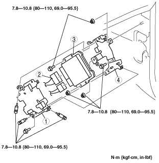
1. Disconnect the battery negative cable.
2. Remove the driver’s side front side trim.
3. Remove in the order indicated in the table.
absggw00001278
|
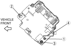
|
1
|
PCM Cover
(See PCM Cover Removal Note.)
(See PCM Cover Installation Note.)
|
|
2
|
PCM Connector
|
|
3
|
PCM
|
|
4
|
Bracket
|
PCM Cover Removal Note
1. Drill the set bolt using a drill bit with a diameter larger than the shank until the head is removed.
2. Clean all foreign material from the PCM connectors.
PCM Cover Installation Note
1. Tighten the PCM cover bolts in the order indicated in the figure.
absggw00001279
|