 |
absggw00000453
ACCELERATOR PEDAL COMPONENT REMOVAL/INSTALLATION [WL-C, WE-C]
id0113b6807300
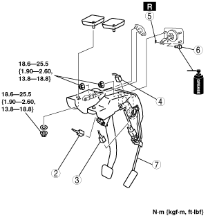
R.H.D.
1. Disconnect the negative battery cable.
2. Set the power brake unit slightly out of the way. (MT) (See POWER BRAKE UNIT REMOVAL/INSTALLATION.)
3. Set the clutch master cylinder slightly out of the way. (MT) (See CLUTCH MASTER CYLINDER REMOVAL/INSTALLATION.)
4. Remove the column cover and steering shaft. (MT) (See STEERING WHEEL AND COLUMN REMOVAL/INSTALLATION.)
5. Remove the 4x4 control module. (4x4, AT)
6. Remove in the order indicated in the table.
7. Install in the reverse order of removal.
MT
absggw00000453
|
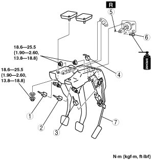
AT
absggw00001971
|
|
1
|
Neutral switch connector
|
|
2
|
Brake switch connector
|
|
3
|
Idle switch connector
|
|
4
|
APP sensor connector
|
|
5
|
Spring pin
|
|
6
|
Clevis pin
|
|
7
|
Accelerator pedal component (See R.H.D..)
|
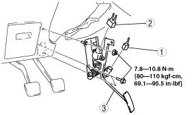
L.H.D.
1. Disconnect the negative battery cable.
2. Remove in the order indicated in the table.
3. Install in the reverse order of removal.
absggw00000454
|
|
1
|
Idle switch connector
|
|
2
|
APP sensor connector
|
|
3
|
Accelerator pedal component
|
Pedal Component Installation Note