 |
absggw00001445
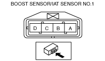
INTAKE AIR TEMPERATURE (IAT) SENSOR NO.1 INSPECTION [WL-C, WE-C]
id0140b7809800
Resistance Inspection
1. Disconnect the boost sensor/IAT sensor No.1 connector.
2. Measure the resistance between IAT sensor No.1 terminals A and B using an ohmmeter.
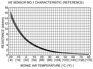
Specification
|
Water temperature (°C {°F}) |
Resistance (kilohm) |
|---|---|
|
20 {68}
|
2.41—2.61
|
|
80 {176}
|
0.32—0.34
|
absggw00001445
|
absggw00001446
|
Circuit Open/Short Inspection
1. Disconnect the boost sensor/IAT sensor No.1 connector.
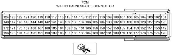
2. Disconnect the PCM connector.(SeePCM REMOVAL/INSTALLATION [WL-C, WE-C].) (See PCM REMOVAL/INSTALLATION (U.K. Specs.) [WL-C, WE-C].)
3. Inspect for an open or short circuit in the following siring harnesses.
absggw00001447
|
absggw00001448
|