|
1
|
VERIFY FREEZE FRAME DATA HAS BEEN RECORDED
• Has the FREEZE FRAME DATA been recorded?
|
Yes
|
Go to the next step.
|
|
No
|
Record the FREEZE FRAME DATA on the repair order, then go to the next step.
|
|
2
|
VERIFY RELATED SERVICE INFORMATION AVAILABILITY
• Verify related Service Information availability.
• Is any related Service Information available?
|
Yes
|
Perform repair or diagnosis according to the available Service Information.
• If the vehicle is not repaired, go to the next step.
|
|
No
|
Go to the next step.
|
|
3
|
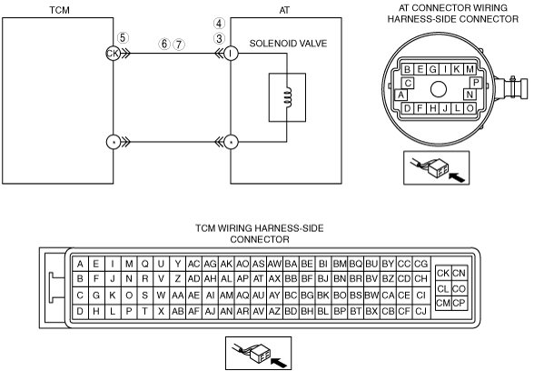
INSPECT AT CONNECTOR FOR POOR CONNECTION
• Turn the engine switch to the LOCK position.
• Inspect AT connector connection.
• Disconnect the AT connector.
• Inspect for poor connection (such as damaged/pulled-out pins, corrosion).
• Is the connection normal?
|
Yes
|
Go to the next step.
|
|
No
|
Repair or replace the connector and/or terminals, then go to Step 8.
|
|
4
|
INSPECT POWER SUPPLY CIRCUIT
• Turn the engine switch to the ON position (engine off).
• Inspect voltage at AT connector terminal H (wiring harness-side).
• Is the voltage approx. 12 V?
|
Yes
|
Go to Step 8.
|
|
No
|
Go to the next step.
|
|
5
|
INSPECT TCM CONNECTOR FOR POOR CONNECTION
• Turn the engine switch to the LOCK position.
• Disconnect the TCM connector.
• Inspect for poor connection (such as damaged/pulled-out pins, corrosion).
• Is the connection normal?
|
Yes
|
Go to the next step.
|
|
No
|
Repair or replace connector and/or terminals, then go to Step 8.
|
|
6
|
INSPECT SOLENOID POWER SUPPLY CIRCUIT FOR OPEN CIRCUIT
• Inspect for continuity between the TCM terminal CK (wiring harness-side) and the AT connector terminal I (wiring harness-side).
• Is there continuity between terminals?
|
Yes
|
Go to the next step.
|
|
No
|
Repair or replace the wiring harness, then go to Step 8.
|
|
7
|
INSPECT SOLENOID POWER SUPPLY CIRCUIT FOR SHORT TO GROUND
• Inspect continuity between AT connector terminal H (wiring harness-side) and body ground.
• Is there continuity?
|
Yes
|
Repair or replace the wiring harness, then go to the Step 8.
|
|
No
|
Go to the next step.
|
|
8
|
VERIFY TROUBLESHOOTING OF DTC P0657 OR P0658 COMPLETED
• Make sure to reconnect all the disconnected connectors.
• Clear the DTC from memory using the IDS/PDS.
• Perform the “After Repair Procedure”.
• Are any DTCs present?
|
Yes
|
Replace the TCM, then go to the next step.
|
|
No
|
Go to the next step.
|
|
9
|
VERIFY DTCS
• Are DTCs except for P0657 and P0658 output?
|
Yes
|
Go to the applicable DTC inspection.
|
|
No
|
DTC troubleshooting completed.
|