DTC P0795, P0798, P0968, P0970, P0971 [5R55S]


id0502c1815500

DTC P0795

Pressure control solenoid C malfunction (low pressure)

DTC P0798

Pressure control solenoid C circuit malfunction (not operation)

DTC P0968

Pressure control solenoid C circuit malfunction (open circuit)

DTC P0970

Pressure control solenoid C circuit malfunction (short to ground)

DTC P0971

Pressure control solenoid C circuit malfunction (short to power supply)

DETECTION CONDITION
•  P0795: Incorrect shift pattern indicating mechanical or hydraulic failure in the transmission.
•  P0798: Incorrect gear ratio in 4GR and 5GR.
•  P0968: Open circuit in circuit between pressure control solenoid C and TCM, or in pressure control solenoid C internal circuit.
•  P0970: Short to ground in circuit between pressure control solenoid C and TCM, or in pressure control solenoid C internal circuit.
•  P0971: Short to power supply in circuit between pressure control solenoid C and TCM, or in pressure control solenoid C internal circuit.
POSSIBLE CAUSE
•  Pressure control solenoid C malfunction.
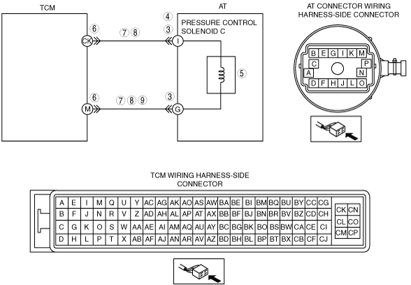
•  Short to ground in wiring harness between AT connector terminal I (wiring harness-side) and TCM terminal CK (wiring harness-side).
•  Short to ground in wiring harness between AT connector terminal G (wiring harness-side) and TCM terminal M (wiring harness-side).
•  Short to power supply in wiring harness between AT connector terminal G (wiring harness-side) and TCM terminal M (wiring harness-side).
•  Open circuit in wiring harness between AT connector terminal I (wiring harness-side) and TCM terminal CK (wiring harness-side).
•  Open circuit in wiring harness between AT connector terminal G (wiring harness-side) and TCM terminal M (wiring harness-side).
•  Damaged connector between AT connector and TCM.
•  TCM malfunction.

Diagnostic procedure

STEP

INSPECTION

ACTION

1
VERIFY FREEZE FRAME DATA HAS BEEN RECORDED
•  Has the FREEZE FRAME DATA been recorded?
Yes
Go to the next step.
No
Record the FREEZE FRAME DATA on the repair order, then go to the next step.
2
VERIFY RELATED SERVICE INFORMATION AVAILABILITY
•  Verify related Service Information availability.
•  Is any related Service Information available?
Yes
Perform repair or diagnosis according to the available Service Information.
•  If the vehicle is not repaired, go to the next step.
No
Go to the next step.
3
INSPECT AT CONNECTOR FOR POOR CONNECTION
•  Turn the engine switch to the LOCK position.
•  Inspect the AT connector connection.
•  Disconnect the AT connector.
•  Inspect for poor connection (such as damaged/pulled-out pins, corrosion).
•  Is the connection normal?
Yes
Go to the next step.
No
Repair or replace the connector and/or terminals, then go to Step 10.
4
INSPECT POWER SUPPLY CIRCUIT
•  Turn the engine switch to the ON position (engine off).
•  Inspect voltage at AT connector terminal I (wiring harness-side).
•  Is the voltage approx. 12 V?
Yes
Go to the next step.
No
Go to Step 6.
5
INSPECT RESISTANCE
•  Turn the engine switch to the LOCK position.
•  Inspect resistance between AT terminal I and G (transmission case side).
•  Is resistance within 3.3—7.5 ohms?
Yes
Go to the next step.
No
Replace the pressure control solenoid C, then go to Step 10.
6
INSPECT TCM CONNECTOR FOR POOR CONNECTION
•  Disconnect the TCM connector.
•  Inspect for poor connection (such as damaged/pulled-out pins, corrosion).
•  Is the connection normal?
Yes
Go to the next step.
No
Repair or replace connector and/or terminals, then go to Step 10.
7
INSPECT PRESSURE CONTROL SOLENOID C CIRCUIT FOR OPEN CIRCUIT
•  Inspect for continuity between the TCM terminal (wiring harness-side) and the AT connector terminal (wiring harness-side).
―  CK and I
―  M and G
•  Is there continuity between terminals?
Yes
Go to the next step.
No
Repair or replace the wiring harness, then go to Step 10.
8
INSPECT PRESSURE CONTROL SOLENOID C CIRCUIT FOR SHORT TO GROUND
•  Inspect for continuity between AT connector terminal (wiring harness-side) and body ground.
―  I and body ground
―  G and body ground
•  Is there continuity?
Yes
Repair or replace the wiring harness, then go to the Step 10.
No
Go to the next step.
9
INSPECT PRESSURE CONTROL SOLENOID C CIRCUIT FOR SHORT TO POWER SUPPLY
•  Turn the engine switch to the ON position (engine off).
•  Inspect the voltage at AT connector terminal G (wiring harness-side).
•  Is the voltage 0 V?
Yes
Go to the next step.
No
Repair or replace the wiring harness, then go to the next step.
10
VERIFY TROUBLESHOOTING OF DTC P0795, P0798, P0968, P0970 OR P0971 COMPLETED
•  Make sure to reconnect all the disconnected connectors.
•  Clear the DTC from memory using the IDS/PDS.
•  Perform the “After Repair Procedure”.
•  Are any DTCs present?
Yes
Replace the TCM, then go to the next step.
No
Go to the next step.
11
VERIFY DTCS
•  Are DTCs except for P0795, P0798, P0968, P0970 and P0971 output?
Yes
Go to the applicable DTC inspection.
No
DTC troubleshooting completed.