CLUTCH UNIT REMOVAL/INSTALLATION [S15M-D, S15MX-D]
id0510008003b3
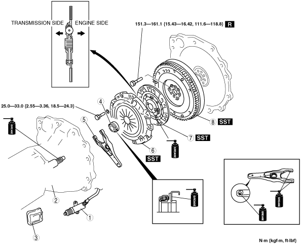
1. Remove in the order indicated in the table.
2. Install in the reverse order of removal.
|
1
|
Clutch release cylinder
|
|
2
|
Manual transmission
|
|
3
|
Boot
|
|
4
|
Clutch release collar
|
|
5
|
Clutch release fork
|
|
6
|
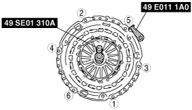
Clutch cover
|
|
7
|
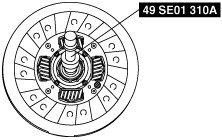
Clutch disc
|
|
8
|
Dual-mass flywheel
|
Clutch Cover and Disc Removal Note
-
Caution
-
• When replacing components, always replace as a complete set.
• Due to the automatic adjustment function of clutch cover, if the old cover assembly is reused, it must be reinstalled together with its original clutch disc.
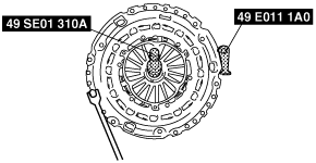
1. Install the SSTs.
2. Loosen each bolt one turn at a time in a crisscross pattern until spring tension is released.
3. Remove the clutch cover and disc.
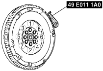
Dual-Mass Flywheel Removal Note
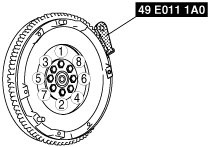
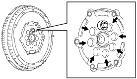
1. Lock the dual-mass flywheel against rotation using the SST (49 E011 1A0).
2. Loosen the lock bolts uniformly and gradually in the order shown in the figure, and remove them.
-
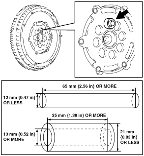
• If the lock bolt installation holes are not positioned properly, perform the following procedure:
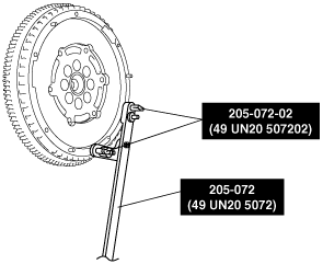
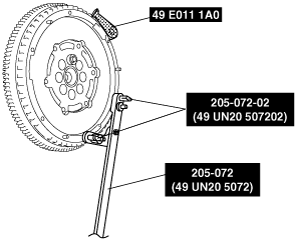
- (1) Install the SST (205-072) and SSTs (205-072-02) or bolts M8×1.25, length 25 mm {0.98 in} to the dual-mass flywheel.
-
- (2) Rotate the dual-mass flywheel (secondary flywheel side) using the SST (205-072).
-
- (3) When the lock bolt installation holes are positioned properly, hold the position and remove one of the lock bolts.
-
- (4) After removing the lock bolt, set up the proper parts and tool as shown in the figure to lock the dual-mass flywheel (secondary flywheel side) against rotation.
-
-
Warning
-
• If all of the lock bolts are removed without locking the dual-mass flywheel (secondary flywheel side) against rotation, the dual-mass flywheel (primary or secondary flywheel side) may rotate, resulting in injury. Therefore, always set up the parts as shown in the figure.
- (5) Remove the remaining lock bolts.
-
3. Remove the dual-mass flywheel.
-
Note
-
• When reusing the dual-mass flywheel, do not remove the parts and tool locking the dual-mass flywheel (secondary flywheel side) against rotation.
4. Remove the SST.
5. Inspect for oil leakage from the crankshaft rear oil seal.
-
• If there is any malfunction, replace the crankshaft rear oil seal.
Dual-Mass Flywheel Installation Note
1. Clean the crankshaft thread holes.
2. Install the dual-mass flywheel to the crankshaft.
3. Temporarily tighten the new lock bolts.
-
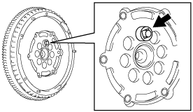
• If the dual-mass flywheel (secondary flywheel side) is not positioned properly, perform the following procedure to install it:
- (1) Temporarily tighten the new lock bolts to the position as shown in the figure.
-
- (2) Lock the dual-mass flywheel against rotation using the SST (49 E011 1A0).
-
- (3) Install the SST (205-072) and SSTs (205-072-02) or bolts M8×1.25, length 25 mm {0.98 in} to the dual-mass flywheel.
-
- (4) After removing the parts and tool as shown in the figure, rotate the dual-mass flywheel (secondary flywheel side) using the SST (205-072) and temporarily tighten the new lock bolt.
-
4. Lock the dual-mass flywheel against rotation using the SST (49 E011 1A0).
5. Tighten the lock bolts uniformly and gradually in the order shown in the figure.
-
Note
-
• Use the SST (205-072) if the dual-mass flywheel (secondary flywheel side) is not positioned properly.
-
Tightening torque
-
151.3—161.1 N·m {15.43—16.42 kgf·m, 111.6—118.8 ft·lbf}
6. Remove the SST.
Clutch Disc Installation Note
1. Hold the clutch disc position using the SST.
Clutch Cover Installation Note
1. Install the SSTs.
2. Tighten the bolts evenly and gradually in a crisscross pattern.
-
Tightening torque
-
25.0—33.0 N·m {2.55—3.36 kgf·m, 18.5—24.3 ft·lbf}