 |
absggw00001183
TRANSMISSION FLUID TEMPERATURE (TFT) SENSOR INSPECTION [5R55S]
id0513c1710300
On-Vehicle Inspection
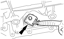
1. Disconnect the negative battery cable.
2. Remove the digital TR sensor insulator.
3. Remove the CKP sensor insulator.
4. Remove the insulator bracket.
5. Disconnect the AT connector.
absggw00001183
|
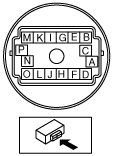
6. Measure resistance between the AT terminals K and L.
absggw00001184
|
Transmission fluid temperature (TFT) sensor
|
ATF temperature (°C {°F}) |
Resistance (kilohm) |
|---|---|
|
-40—-20 {-40—-4}
|
284—967
|
|
-19—-1 {-3—30}
|
100—284
|
|
0—20 {32—68}
|
37—100
|
|
21—40 {70—104}
|
16—37
|
|
41—70 {106—158}
|
5—16
|
|
71—90 {160—194}
|
2.7—5
|
|
91—110 {196—230}
|
1.5—2.7
|
|
111—130 {232—266}
|
0.8—1.5
|
|
131—150 {268—302}
|
0.54—0.8
|
7. Connect the AT connector.
8. Remove the insulator bracket. (See AUTOMATIC TRANSMISSION REMOVAL/INSTALLATION [5R55S].)
9. Remove the CKP sensor insulator. (See AUTOMATIC TRANSMISSION REMOVAL/INSTALLATION [5R55S].)
10. Remove the digital TR sensor insulator. (See AUTOMATIC TRANSMISSION REMOVAL/INSTALLATION [5R55S].)
11. Connect the negative battery cable.
Off-Vehicle Inspection
1. Remove the solenoid body. (See SOLENOID BODY REMOVAL/INSTALLATION [5R55S].)
2. Place the solenoid body and a thermometer in ATF as shown in the figure, and heat the ATF gradually.
3. Measure the resistance between the solenoid body terminals K and L.
absggw00001185
|
Transmission fluid temperature (TFT) sensor
|
ATF temperature (°C {°F}) |
Resistance (kilohm) |
|---|---|
|
-40—-20 {-40—-4}
|
284—967
|
|
-19—-1 {-3—30}
|
100—284
|
|
0—20 {32—68}
|
37—100
|
|
21—40 {70—104}
|
16—37
|
|
41—70 {106—158}
|
5—16
|
|
71—90 {160—194}
|
2.7—5
|
|
91—110 {196—230}
|
1.5—2.7
|
|
111—130 {232—266}
|
0.8—1.5
|
|
131—150 {268—302}
|
0.54—0.8
|
4. Install the solenoid body. (See SOLENOID BODY REMOVAL/INSTALLATION [5R55S].)