 |
absggw00001975
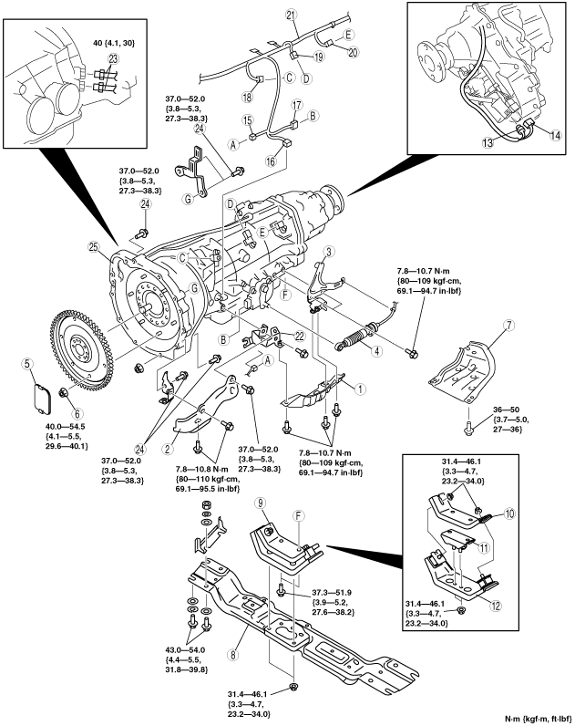
AUTOMATIC TRANSMISSION REMOVAL/INSTALLATION [5R55S]
id0513c1249200
1. Disconnect the negative battery cable.
2. Drain the ATF. (See AUTOMATIC TRANSMISSION FLUID (ATF) REPLACEMENT [5R55S].)
3. Remove the following parts.
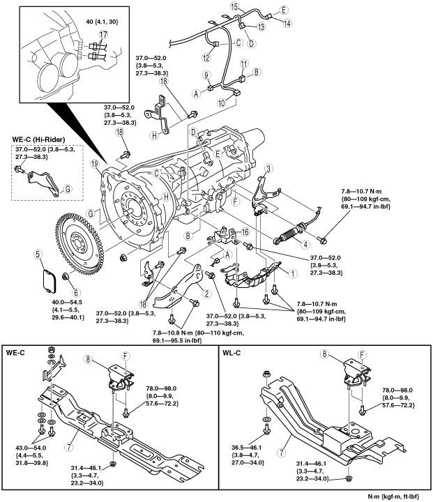
4. Remove in the order indicated in the table.
5. Install in the reverse order of removal.
6. Add ATF and, with the engine idling, inspect the ATF level and inspect for leakage. (See AUTOMATIC TRANSMISSION FLUID (ATF) REPLACEMENT [5R55S].) (See AUTOMATIC TRANSMISSION FLUID (ATF) INSPECTION [5R55S].)
7. Inspect selector lever operation. (See SELECTOR LEVER INSPECTION.)
8. Inspect for leakage of ATF from all connecting points.
9. Perform the mechanical system test. (See MECHANICAL SYSTEM TEST [5R55S].)
|
Service item |
Test item |
|
|---|---|---|
|
Line pressure test |
Stall speed test |
|
|
Automatic transmission replacement
|
×
|
|
|
Automatic transmission overhaul
|
×
|
×
|
|
Control valve body replacement
|
×
|
×
|
|
Torque converter replacement
|
×
|
×
|
|
Fluid pump replacement
|
×
|
|
|
Clutch system replacement
|
×
|
|
10. Perform the road test. (See ROAD TEST [5R55S].)
4x2
absggw00001975
|
|
1
|
Insulator
|
|
2
|
Insulator
|
|
3
|
Selector cable bracket
|
|
4
|
Selector cable
|
|
5
|
Cover
|
|
6
|
Torque converter installation nuts
|
|
7
|
Crossmember
(See Transmission Removal Note.)
|
|
8
|
Transmission mount rubber
|
|
9
|
CKP sensor connector
|
|
10
|
AT connector
|
|
11
|
Digital TR sensor connector
|
|
12
|
TSS sensor connector
|
|
13
|
ISS sensor connector
|
|
14
|
OSS sensor connector
|
|
15
|
Wiring harness
|
|
16
|
Insulator bracket
|
|
17
|
Oil pipe
(See Oil Pipe Removal Note.)
(See Oil Pipe Installation Note.)
|
|
18
|
Transmission installation bolt and nut
|
|
19
|
Transmission
(See Transmission Removal Note.)
|
4x4
absggw00001976
|
|
1
|
Insulator
|
|
2
|
Insulator
|
|
3
|
Selector cable bracket
|
|
4
|
Selector cable
|
|
5
|
Cover
|
|
6
|
Torque converter installation nuts
|
|
7
|
Transfer case under cover
|
|
8
|
Crossmember
(See Transmission Removal Note.)
|
|
9
|
Transmission mount component
|
|
10
|
Transmission mount upper
|
|
11
|
Transmission rubber
|
|
12
|
Transmission mount lower
|
|
13
|
Transfer case motor connector
|
|
14
|
Transfer case speed sensor connector
|
|
15
|
CKP sensor connector
|
|
16
|
AT connector
|
|
17
|
Digital TR sensor connector
|
|
18
|
TSS sensor connector
|
|
19
|
ISS sensor connector
|
|
20
|
OSS sensor connector
|
|
21
|
Wiring harness
|
|
22
|
Insulator bracket
|
|
23
|
Oil pipe
(See Oil Pipe Removal Note.)
(See Oil Pipe Installation Note.)
|
|
24
|
Transmission installation bolt and nut
|
|
25
|
Transmission and transfer case
(See Transmission Removal Note.)
|
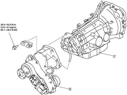
4x4
absggw00001540
|
|
26
|
Transfer case
|
|
27
|
Transmission
|
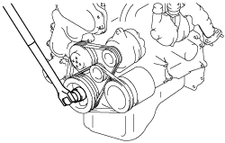
Torque Converter Installation Nuts Removal Note
1. Remove the cooling fan. (See COOLING FAN REMOVAL/INSTALLATION [WL-C, WE-C].)
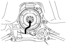
2. Hold the crankshaft pulley to prevent the drive plate from rotating.
absggw00001804
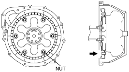
|
3. Remove the torque converter nuts.
absggw00001805
|
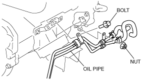
Oil Pipe Removal Note
1. Remove the oil pipe installation bolt and nut.
absggw00001810
|
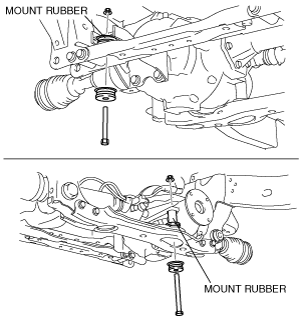
Transmission Removal Note
1. Remove the front differential mount rubber.
absggw00001541
|
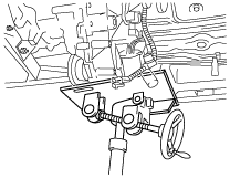
2. Support the transfer case side securely using one transmission jack.
absggw00001806
|
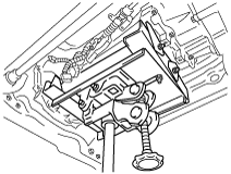
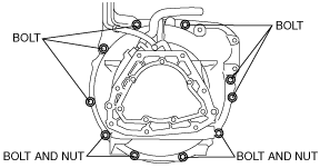
3. Remove the crossmember.
4. Support the transmission securely using a transmission jack.
absggw00001807
|
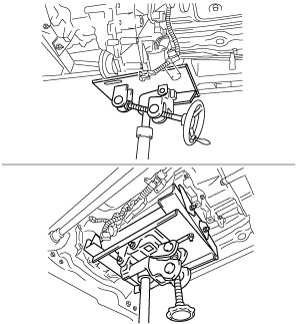
5. Support the front side of engine securely using a transmission jack.
6. Remove the transmission installation bolt.
absggw00001542
|
7. Remove the transmission while setting it out of the way so that it does not contact the differential.
absggw00001543
|
Transmission Installation Note
1. Support the front side of engine securely using a transmission jack.
2. Support the transmission and transfer case securely using a transmission jack.
absggw00001808
|
3. Install the transmission while setting it out of the way so that it does not contact the differential.
absggw00001544
|
4. Tighten the transmission installation bolts and nuts.
absggw00001542
|
5. Install the front differential mount rubber.
absggw00001541
|
Oil Pipe Installation Note
1. Install the oil pipe installation bolt and nut.
absggw00001810
|
Torque Converter Installation Nuts Installation Note
1. Hold the crankshaft pulley to prevent the drive plate from rotating.
absggw00001804
|
2. Tighten the new torque converter installation nuts.
absggw00001805
|