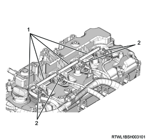
1. Component views
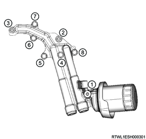
Fuel supply pump
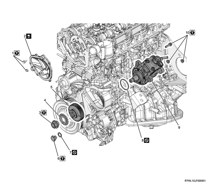
Part name
- Nut and bolt
- Timing chain lower cover
- Supply pump gear nut
- Supply pump sprocket
- Supply pump gear
- Plug
- Gasket
- O-ring
- Fuel supply pump
- Nut and bolt
Tightening torque
1: 10 N・m { 1.0 kgf・m / 89 lb・in }
3: 130 N・m { 13.3 kgf・m / 96 lb・ft }
6: 50 N・m { 5.1 kgf・m / 37 lb・ft }
10: 25 N・m { 2.5 kgf・m / 18 lb・ft }
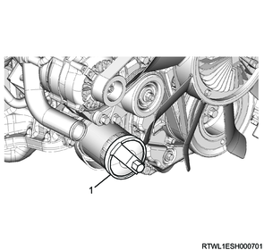
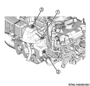
2. Fuel supply pump installation
1) Apply soapy water to the O-ring.
Caution
- Do not reuse the O-ring.
2) Install the O-ring to the fuel supply pump.
Caution
- Do not pinch the O-ring.
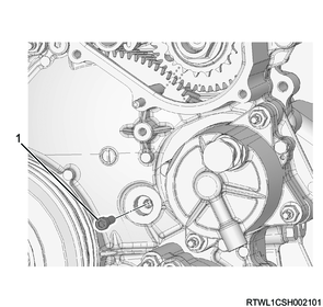
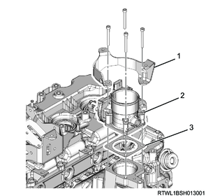
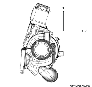
3) Install the fuel supply pump to the timing gear case.
Tightening torque: 25 N・m { 2.5 kgf・m / 18 lb・ft }
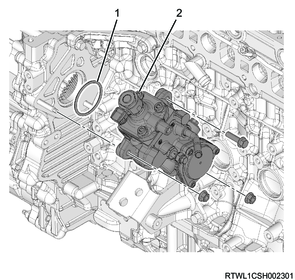
Legend
- O-ring
- Fuel supply pump
4) Align 3 marks on the supply pump gear and idle gear A, and install the supply pump gear to the supply pump shaft.
Caution
- Check that the supply pump gear is securely engaged with the main and sub gears of idle gear A.
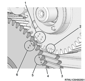
Legend
- Supply pump installation or removal position (Supply pump gear side)
- TDC position (Supply pump gear side)
- Sub-gear
- Sub-gear
- TDC position (Idle gear A side)
- Supply pump installation or removal position (Idle gear A side)
5) Install the special tool to the starter installation section of the rear plate.
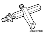
SST: 5-8840-0214-0 - crankshaft stopper
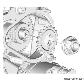
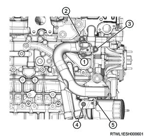
6) Align the supply pump gear dowel pin with the notched section of the supply pump sprocket, and then install the supply pump sprocket to the supply pump gear.
Tightening torque: 130 N・m { 13.3 kgf・m / 96 lb・ft }
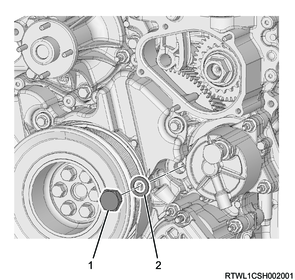
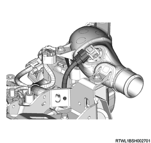
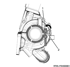
7) Connect the connector to the fuel supply pump.
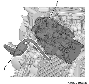
Legend
- Fuel supply pump connector
- Fuel supply pump
8) Remove the special tool from the starter installation section of the rear plate.
3. Timing chain installation
1) Install the idle gear D sprocket and timing chain as a set to idle gear D and the supply pump gear sprocket.
Tightening torque: 8.0 N・m { 0.8 kgf・m / 71 lb・in }
2) Install the idle gear D center bolt and sleeve to the idle gear D shaft.
Tightening torque: 59 N・m { 6.0 kgf・m / 44 lb・ft }
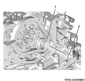
Legend
- Sleeve
- Idle gear D center bolt
3) Align the idle gear D alignment mark with the blue link of the timing chain.
4) Install the timing chain to the supply pump sprocket.
5) Align the supply pump sprocket alignment mark with the yellow plate position of the timing chain.

Legend
- Timing chain
- Timing mark
- Blue link
- Yellow link
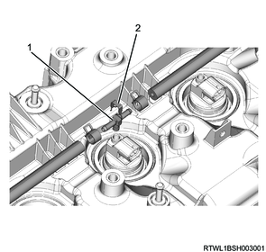
6) Install the timing chain lever pivot to the timing chain tension lever.
Tightening torque: 27 N・m { 2.8 kgf・m / 20 lb・ft }
7) Push down the timing chain tensioner latch and insert the plunger.
Note
- Install the hook to the pin while pressing the plunger.
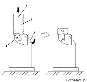
Legend
- Pin
- Plunger
- Latch
- Hook
8) Install the oil feed pipe to the cylinder block.
Caution
- Do not reuse the gasket.
Tightening torque: 54 N・m { 5.5 kgf・m / 40 lb・ft } Eyebolt
Tightening torque: 25 N・m { 2.5 kgf・m / 18 lb・ft } Bracket
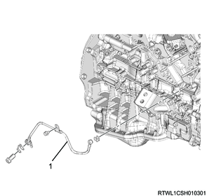
Legend
- Oil feed pipe
9) Install the timing chain tensioner and gasket to the cylinder head.
Caution
- Do not reuse the gasket.
Tightening torque: 10 N・m { 1.0 kgf・m / 89 lb・in }
10) Install the oil feed pipe to the timing chain tensioner.
Caution
- Do not reuse the gasket.
Tightening torque: 14.7 N・m { 1.5 kgf・m / 11 lb・ft }
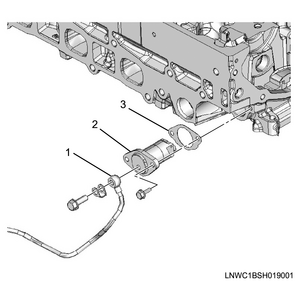
Legend
- Oil feed pipe
- Timing chain tensioner
- Gasket
11) Remove the M6 lock bolt from idle gear A.
Caution
- Do not forget to remove the lock bolt.
Legend
- M6 lock bolt
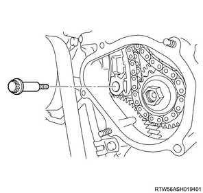
12) Install the plug to the gear case cover.
Caution
- Do not reuse the gasket.
Tightening torque: 50 N・m { 5.1 kgf・m / 37 lb・ft }
Legend
- Plug
- Gasket
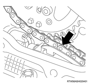
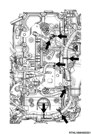
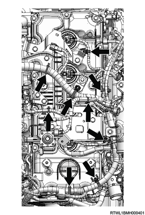
13) Lightly press the area indicated by the arrow in the diagram to disconnect the hook from the pin.
Note
- The hook of the tensioner opens and the plunger pushes the tension lever to pull the chain.
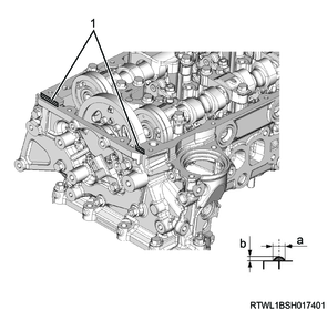
4. Timing chain lower cover installation
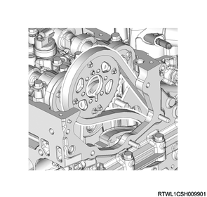
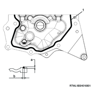
1) Referring to the diagram, apply ThreeBond 1207C or equivalent to the timing chain lower cover.
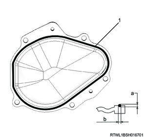
Legend
- Liquid gasket
Standard value
a: 2.0 to 2.5 mm { 0.079 to 0.098 in } Bead height
b: 2.0 to 2.5 mm { 0.079 to 0.098 in } Bead width
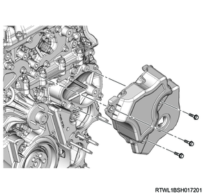
2) Install the timing chain lower cover to the gear case cover.
Tightening torque: 10.0 N・m { 1.0 kgf・m / 89 lb・in }
3) Install the noise cover to the timing chain lower cover.
Tightening torque: 10.0 N・m { 1.0 kgf・m / 89 lb・in }
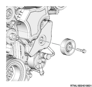
4) Install the idle pulley to the timing chain lower cover.
Tightening torque: 51 N・m { 5.2 kgf・m / 38 lb・ft }
5. Timing chain upper cover installation
1) Referring to the diagram, apply ThreeBond 1207C or equivalent to the timing chain upper cover.
Caution
- Install the timing chain cover within 5 minutes of applying the liquid gasket.
Legend
- Liquid gasket
Standard value
a: 1.0 to 1.5 mm { 0.039 to 0.059 in } Bead height
b: 2.0 to 2.5 mm { 0.079 to 0.098 in } Bead width
2) Install the timing chain upper cover to the cylinder head.
Caution
- Wipe off any excess liquid gasket.
Tightening torque: 25 N・m { 2.5 kgf・m / 18 lb・ft }
3) Connect the connector to the CMP sensor.
4) Install the idle pulley to the timing chain upper cover.
Tightening torque: 51 N・m { 5.2 kgf・m / 38 lb・ft }
6. Cylinder head cover installation
1) Apply the engine oil to the oil seal.
2) Insert the oil seal from the lower side of the cylinder head cover until it reaches the far end.
3) Referring to the diagram, apply ThreeBond 1217H or 1207C to the cylinder head mating surface.
Caution
- Install the cylinder head cover within 5 minutes of applying liquid gasket.
- Remove any dirt or dust from the oil seal section on the injector connector side.
Legend
- Liquid gasket
Standard value
a: 2.0 to 2.5 mm { 0.079 to 0.098 in } Bead width
b: 1.0 to 1.5 mm { 0.039 to 0.059 in } Bead height
4) Temporarily tighten the cylinder head cover to the cylinder head in the order shown in the diagram.
Caution
- Do not reuse the gasket.
Tightening torque: 5.0 N・m { 0.5 kgf・m / 44 lb・in }
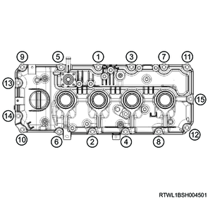
5) Final tighten the cylinder head cover to the cylinder head in the order shown in the diagram.
Tightening torque: 9.0 N・m { 0.9 kgf・m / 80 lb・in }
6) Install the harness bracket to the cylinder head cover.
Note
- For models with urethane covers, install together with the urethane cover.
- When installing the urethane cover, remove the oil filler cap before performing work.
Tightening torque: 25 N・m { 2.5 kgf・m / 18 lb・ft } Harness bracket
Models with urethane covers
Legend
- Filler cap
- Harness bracket
- Urethane cover
7) Connect the harness clip to the cylinder head cover.
RHD
LHD
8) Connect the PCV hose to the cylinder head cover.
7. Glow plug installation
1) Install the glow plug to the cylinder head.
Tightening torque: 18 N・m { 1.8 kgf・m / 13 lb・ft }

Legend
- Glow plug
2) Connect the connector to the glow plug.
Legend
- Connector
8. Intake throttle valve installation
1) Install the following parts to the inlet manifold.
- Air duct bracket
- Intake throttle valve
- Gasket
Caution
- Do not reuse the gasket.
Tightening torque: 10.0 N・m { 1.0 kgf・m / 89 lb・in }
Legend
- Air duct bracket
- Intake throttle valve
- Gasket
2) Connect the connector to the intake throttle valve.
9. Fuel leak-off hose installation
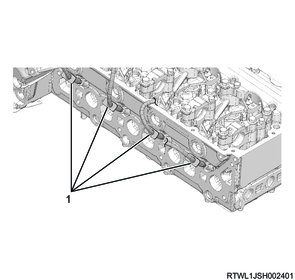
1) Install the injector leak-off pipe to the injector.
Caution
- Do not reuse the injector leak-off pipe or clip.
Legend
- Injector leak-off pipe
- Clip
2) Install the fuel leak-off hose to the leak-off pipe.
3) Connect the connector to the injector.
Legend
- Fuel leak-off hose
- Injector connector
10. Air duct bracket installation
1) Install the air duct bracket to the cylinder head cover.
Tightening torque: 25 N・m { 2.5 kgf・m / 18 lb・ft }
11. Intake air duct installation
1) Install the intake duct to the intake throttle valve.
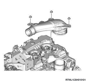
2) Connect the connector to the boost pressure sensor.
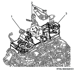
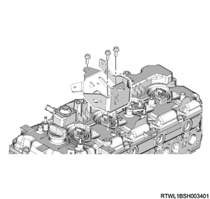
12. Differential pressure sensor bracket installation
1) Install the differential pressure sensor bracket to the cylinder head cover.
Tightening torque: 25 N・m { 2.5 kgf・m / 18 lb・ft }
2) Install the harness bracket to the cylinder head cover.
Tightening torque: 25 N・m { 2.5 kgf・m / 18 lb・ft }
3) Connect the following sensor harnesses to the harness bracket.
- Exhaust gas temperature sensor 1 (Front of DPD filter)
- Exhaust gas temperature sensor 2 (Front of oxidation catalyst)
- Heated oxygen sensor
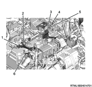
Legend
- Harness bracket
- Exhaust gas temperature sensor 1 (Front of DPD filter)
- Differential pressure sensor bracket
- Heated oxygen sensor
- Exhaust gas temperature sensor 2 (Front of oxidation catalyst)
- Harness bracket
13. Exhaust differential pressure sensor installation
14. Starter motor installation
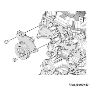
15. Tension pulley installation
1) Install the tension pulley to the cylinder head.
Tightening torque: 25 N・m { 2.5 kgf・m / 18 lb・ft }
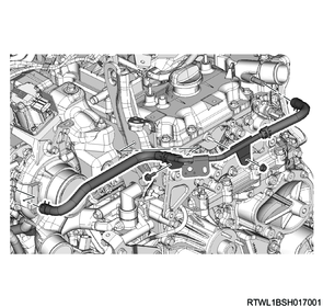
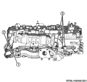
16. Water pipe installation
1) Install the water pipe to the following parts.
- Thermostat
- Cylinder head
- Turbocharger
Tightening torque: 10.0 N・m { 1.0 kgf・m / 89 lb・in } Bolt, nut
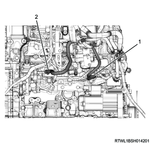
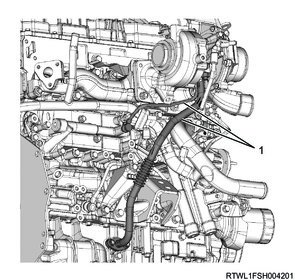
17. Fuel leak-off pipe installation
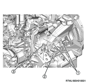
1) Install the fuel leak-off pipe to the fuel supply pump and common rail (fuel rail).
Tightening torque: 10.3 N・m { 1.1 kgf・m / 91 lb・in } Fuel supply pump side
Tightening torque: 25 N・m { 2.5 kgf・m / 18 lb・ft } Cylinder block side
Tightening torque: 10.3 N・m { 1.1 kgf・m / 91 lb・in } Common rail (fuel rail) side

Legend
- Leak-off hose
- Fuel leak-off pipe
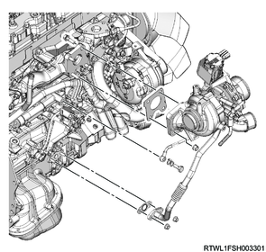
18. Fuel feed pipe installation
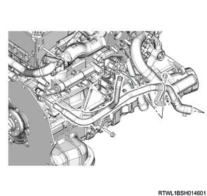
1) Install the fuel feed pipe to the fuel supply pump and common rail (fuel rail).
Caution
- Do not reuse the fuel feed pipe.
Tightening torque: 44 N・m { 4.5 kgf・m / 32 lb・ft }

Legend
- Fuel supply pump
- Fuel feed pipe
- Common rail (fuel rail)
19. Fuel hose connect
1) Connect the fuel return hose to the fuel leak-off pipe.
2) Connect the fuel feed hose to the fuel supply pump.
Legend
- Fuel return hose
- Fuel feed hose
20. EGR cooler bypass control solenoid valve installation
1) Install the EGR cooler bypass control solenoid valve and bracket as a set to the inlet manifold.
Tightening torque: 25 N・m { 2.5 kgf・m / 18 lb・ft }
2) Connect the vacuum hose to the EGR cooler bypass control solenoid valve.
3) Connect the connector to the EGR cooler bypass control solenoid valve.

Legend
- EGR cooler bypass control solenoid valve
21. A/C compressor bracket installation
1) Temporarily tighten the A/C compressor bracket to the cylinder head.
2) Final tighten the A/C compressor bracket to the cylinder head in the order shown in the diagram.
Tightening torque: 25 N・m { 2.5 kgf・m / 18 lb・ft }
22. A/C compressor connect
1) Connect the A/C compressor to the A/C compressor bracket.
Tightening torque: 51 N・m { 5.2 kgf・m / 38 lb・ft }
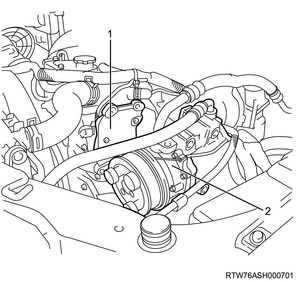
Legend
- A/C compressor bracket
- A/C compressor
23. EGR water pipe installation
1) Install the EGR water pipe to the oil cooler and turbocharger lower bracket.
Tightening torque: 25 N・m { 2.5 kgf・m / 18 lb・ft }
2) Connect the water hose to the water intake pipe and return hose.
24. Oil filter installation
1) Temporarily tighten the oil filter and gasket to the oil cooler in the order shown in the diagram.
Caution
- Do not reuse the gasket.
- Ensure that no dirt or foreign material enters.
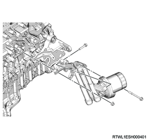
2) Final tighten the oil filter to the oil cooler in the order shown in the diagram.
Tightening torque: 25 N・m { 2.5 kgf・m / 18 lb・ft }
25. Oil filter element installation
1) Clean the oil filter mounting surface.
2) Apply grease or engine oil to the oil filter element seal section.
3) Install the oil filter element to the oil filter bracket using the special tool.
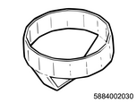
SST: 5-8840-0203-0 - oil filter wrench
Tightening torque: 19.6 N・m { 2.0 kgf・m / 14 lb・ft }
Legend
- 5-8840-0203-0
26. Water intake pipe installation
1) Temporarily tighten the water intake pipe and water hose to the oil cooler in the order shown in the diagram.
Caution
- Do not reuse the gasket.
2) Final tighten the water intake pipe and water hose to the oil cooler in the order shown in the diagram.
Tightening torque: 25 N・m { 2.5 kgf・m / 18 lb・ft }
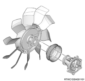
27. Cooling fan installation
1) Install the fan pulley to the water pump.
2) Install the cooling fan and cooling fan clutch as a set to the water pump.
Tightening torque: 10.0 N・m { 1.0 kgf・m / 89 lb・in }
28. Generator installation
1) Install the generator to the lower bracket.
Tightening torque: 40 N・m { 4.1 kgf・m / 30 lb・ft }

2) Install the upper bracket to the generator and timing gear case.
Tightening torque: 25 N・m { 2.5 kgf・m / 18 lb・ft }
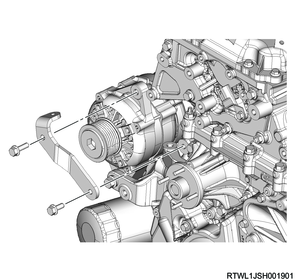
3) Connect the connector to the generator.
4) Connect the B-terminal to the generator.
Tightening torque: 12 N・m { 1.2 kgf・m / 106 lb・in }
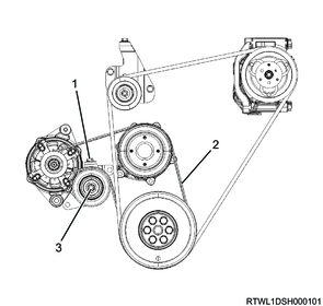
29. Cooling fan belt installation
1) Install the cooling fan belt to the following parts.
- Fan pulley
- Generator
- Crankshaft pulley
MT models

Legend
- Adjust bolt
- Cooling fan belt
- Lock nut
AT models
Legend
- Adjust bolt
- Cooling fan belt
- Lock nut
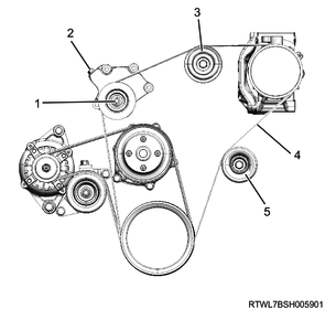
30. A/C compressor drive belt installation
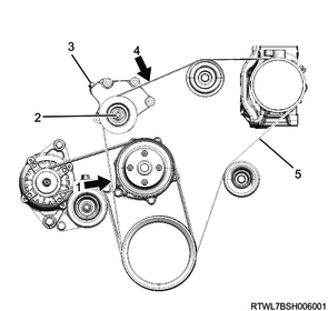
1. M/T models (Euro 5 or above)
1) Install the A/C compressor drive belt to the following parts.
- Tension pulley
- A/C compressor
- Crankshaft pulley
- Idle pulley
Legend
- Lock nut
- Adjust bolt
- Idle pulley
- A/C compressor drive belt
- Idle pulley
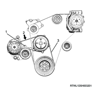
2. Except M/T models (Euro 5 or above)
1) Install the A/C compressor drive belt to the following parts.
- Tension pulley
- A/C compressor
- Crankshaft pulley
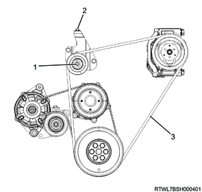
Legend
- Lock nut
- Adjust bolt
- A/C compressor drive belt
31. Turbocharger installation
1) Feed 1 cc (approximately 20 drops) of engine oil into the oil feed port.
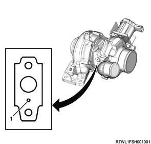
Legend
- Oil feed port
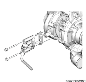
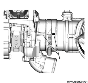
2) Install the turbocharger oil pipe and gasket to the turbocharger.
Caution
- Do not reuse the gasket.
Tightening torque: 10.0 N・m { 1.0 kgf・m / 89 lb・in }
Legend
- Turbocharger oil pipe
- Bolt
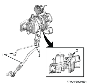
3) Install the water feed and return pipe, as well as the gasket to the turbocharger.
Caution
- Do not reuse the gasket.
Tightening torque: 10.0 N・m { 1.0 kgf・m / 89 lb・in }
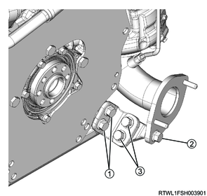
4) Install the following parts as a set to the exhaust manifold.
- Turbocharger
- Turbocharger oil pipe
- Water feed and return pipe
Caution
- Do not reuse the gasket.
Tightening torque: 52 N・m { 5.3 kgf・m / 38 lb・ft }
5) Connect the connector to the turbocharger.
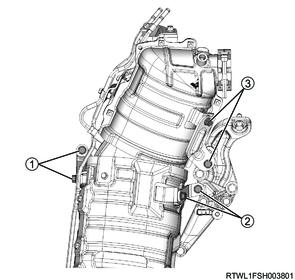
32. Turbocharger bracket installation
1) Install the turbocharger bracket to the cylinder block.
Tightening torque: 51 N・m { 5.2 kgf・m / 38 lb・ft } M10
Tightening torque: 25 N・m { 2.5 kgf・m / 18 lb・ft } M8

Legend
- Turbocharger bracket
33. Turbocharger oil pipe connect
1) Connect the turbocharger oil pipe to the oil cooler and crankcase.
Caution
- Do not reuse the gasket.
Tightening torque: 25 N・m { 2.5 kgf・m / 18 lb・ft } Crankcase side
Tightening torque: 23 N・m { 2.3 kgf・m / 17 lb・ft } Oil cooler side
Legend
- Turbocharger oil pipe
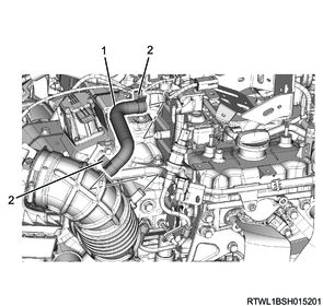
34. Turbocharger water hose connect
1) Connect the turbocharger water return hose to the water feed and return pipe.
2) Connect the turbocharger water feed hose to the water feed and return pipe.

Legend
- Turbocharger water feed hose
- Turbocharger water return hose
35. EGR cooler installation
1) Temporarily tighten the EGR duct and gasket to the EGR cooler in the order shown in the diagram.
Caution
- Do not reuse the gasket.
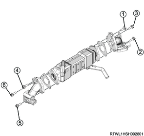
2) Final tighten the EGR duct to the EGR cooler in the order shown in the diagram.
Tightening torque: 27 N・m { 2.8 kgf・m / 20 lb・ft }
3) Install the EGR duct gasket to the cylinder head.
Caution
- Do not reuse the gasket.
Note
- Face the protruding section of the gasket toward the upper side of the engine.

Legend
- Protrusion
4) Temporarily tighten the EGR cooler and gasket to the cylinder head and exhaust manifold in the order shown in the diagram.
Caution
- Do not reuse the gasket.
5) Final tighten the EGR cooler to the cylinder head and exhaust manifold in the order shown in the diagram.
Tightening torque: 27 N・m { 2.8 kgf・m / 20 lb・ft }
6) Install the harness bracket to the EGR duct.
Tightening torque: 25 N・m { 2.5 kgf・m / 18 lb・ft }
7) In the order shown in the diagram, temporarily tighten the heat protector to the EGR duct.
8) In the order shown in the diagram, final tighten the heat protector to the EGR duct.
Tightening torque: 25 N・m { 2.5 kgf・m / 18 lb・ft }
36. EGR cooler water hose connect
1) Connect the EGR cooler water return hose to the EGR cooler.
2) Connect the EGR cooler water feed hose to the EGR cooler.

Legend
- EGR cooler water return hose
- EGR cooler water feed hose
37. Air cleaner installation
1) Install the air cleaner to the vehicle.
Tightening torque: 20 N・m { 2.0 kgf・m / 15 lb・ft }
2) Connect the connector to the MAF and IAT sensor.
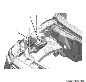
Legend
- Air cleaner
- MAF and IAT sensor
38. Battery installation
1) Install the battery to vehicle.
2) Install the battery bracket to the frame.
Tightening torque: 4.0 N・m { 0.41 kgf・m / 35.4 lb・in } Battery side
Tightening torque: 20 N・m { 2.0 kgf・m / 15 lb・ft } Frame side
3) Connect the battery cable to the battery.
4) Connect the battery ground cable to the frame.
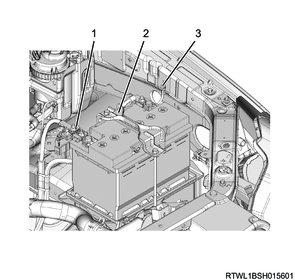
Legend
- Battery cable
- Battery bracket
- Battery ground cable
39. Air duct installation
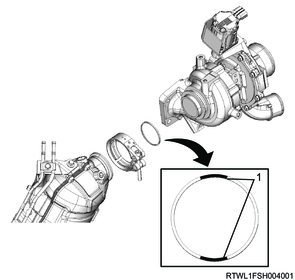
1) Align the air duct with the air cleaner and turbocharger.
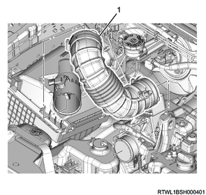
Legend
- Air duct
2) Referring to the diagram, align the alignment mark positions and connect the air duct to the turbocharger.
Tightening torque: 4.0 N・m { 0.4 kgf・m / 35 lb・in }
Legend
- Alignment mark
3) Install the PCV hose to the cylinder head cover and air duct.
Caution
- Align the marks on the pipe side and hose side.
Legend
- PCV hose
- Clamp
40. DPD installation
1) Temporarily tighten the DPD and exhaust pipe bracket to the crankcase in the order shown in the diagram.
2) Temporarily tighten the DPD bracket to the following parts in the order shown in the diagram.
- DPD
- Oil cooler side bracket
- Turbocharger lower bracket
- Turbocharger upper bracket
3) Temporarily tighten the DPD to the turbocharger using a V-band.
Caution
- Do not reuse the gasket.
- Assemble with the gasket yellow paint section facing toward the DPD.
Legend
- Yellow paint section
V-band assembly direction
Legend
- Top
- RH
4) Final tighten the DPD and exhaust pipe bracket to the crankcase in the order shown in the diagram.
Tightening torque: 94 N・m { 9.6 kgf・m / 69 lb・ft }
5) Final tighten the DPD bracket to the following parts in the order shown in the diagram.
- DPD
- Oil cooler side bracket
- Turbocharger lower bracket
- Turbocharger upper bracket
Tightening torque: 25 N・m { 2.5 kgf・m / 18 lb・ft }
6) Align the markings, and then connect the differential pressure hoses to the DPD.
Caution
- Install the differential pressure hose clip securely so that there is no gas leakage.
- Do not use cracked hoses.
- If there is gas leakage from connections, the sensor may malfunction.
- After starting the engine, verify that there is no gas leakage.

Legend
- White paint
- Green paint
7) Final tighten the V-band to the DPD and turbocharger.
Note
- Turn the V-band bolt, pushing it into the joint pin.
Caution
- Tighten in 2 stages.
Tightening torque: 12 N・m { 1.2 kgf・m / 106 lb・in }
Legend
- V-band bolt
- Joint pin
8) Install the heat protector to the turbocharger.
Tightening torque: 25 N・m { 2.5 kgf・m / 18 lb・ft }

Legend
- Heat protector
41. Exhaust pipe installation
42. Radiator installation
43. Fuel air bleed
1) Open the engine hood.
2) Press the priming pump until it becomes hard.
Caution
- Completely bleed air, as insufficient air bleeding may lead to engine malfunctions.
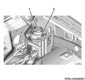
Legend
- Priming pump
- Fuel filter with sedimenter
44. Cooling fan belt adjustment
When installing a new belt, initial stretching of the belt occurs.
In addition, when reusing the belt, the belt needs to be fitted to the pulley groove.
After fitting the cooling fan belt, readjust the cooling fan belt tension.
1) Loosen the tension pulley lock nut using a wrench.
2) Adjust the cooling fan belt tension by turning the adjust bolt.
Note
- The standard amount of deflection shown is the value obtained when the standard pressure is applied to the midpoint of the fan pulley and generator.
Standard: 98 N { 10.0 kg / 22 lb }
Caution
- Accurately adjust the tension as there is a possibility the service life of the belt may be shortened or belt squeal may be generated if the tension is not within the appropriate range.
- Use a sonic tension meter to verify accurate tension adjustment.
| Adjustment conditions |
Deflection |
Vibration frequency |
| When new |
5.0 to 6.0 mm { 0.20 to 0.24 in } |
207 to 231 Hz |
| Reused |
7.0 to 7.8 mm { 0.28 to 0.31 in } |
176 to 190 Hz |
Legend
- Tension pulley adjust bolt
- Measurement point
- Cooling fan belt
3) Tighten the tension pulley lock nut to the specified torque.
Tightening torque: 41 N・m { 4.2 kgf・m / 30 lb・ft }
45. A/C compressor drive belt adjustment
When installing a new belt, initial stretching of the belt occurs.
In addition, when reusing the belt, the belt needs to be fitted to the pulley groove.
After fitting the A/C compressor drive belt, adjust the tension of the A/C compressor drive belt again.
1) Loosen the tension pulley lock nut.
2) Turn the tension pulley adjust bolt to adjust the tension.
Note
- The standard deflection shown is the value obtained when the specified load is applied to the measurement point of the A/C compressor drive belt.
98 N { 10.0 kg / 22 lb } Load
Caution
- Accurately adjust the tension as there is a possibility the service life of the belt may be shortened or belt squeal may be generated if the tension is not within the appropriate range.
- Use a sonic tension meter to verify accurate tension adjustment.
| Adjustment conditions |
Deflection |
Vibration frequency |
| When new |
10.2 to 11.2 mm { 0.40 to 0.44 in } |
163 to 179 Hz |
| Reused |
12.1 to 13.3 mm { 0.48 to 0.52 in } |
131 to 147 Hz |
| Adjustment conditions |
Deflection |
Vibration frequency |
| When new |
6.8 to 7.4 mm { 0.27 to 0.29 in } |
249 to 273 Hz |
| Reused |
7.9 to 8.7 mm { 0.31 to 0.34 in } |
201 to 225 Hz |
Legend
- Measurement point 1
- Lock nut
- Adjust bolt
- Measurement point 4
- A/C compressor drive belt
3) Tighten the tension pulley lock nut to the specified torque.
Tightening torque: 51 N・m { 5.2 kgf・m / 38 lb・ft }