1. Component views
Inlet manifold
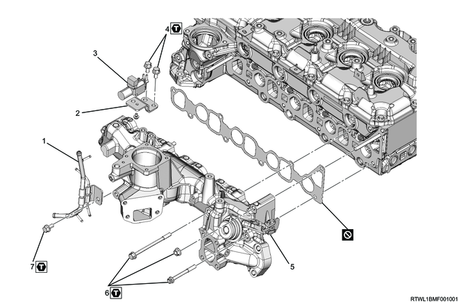
Part name
- Vacuum pipe
- Bracket
- Swirl control solenoid valve
- Bolt
- Inlet manifold
- Nut and bolt
- Bolt
Tightening torque
4: 25 N・m { 2.5 kgf・m / 18 lb・ft }
6: 25 N・m { 2.5 kgf・m / 18 lb・ft }
7: 25 N・m { 2.5 kgf・m / 18 lb・ft }
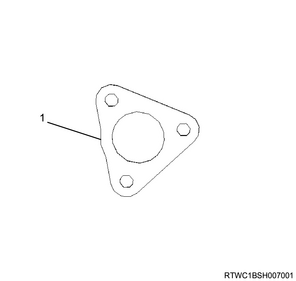
2. Inlet manifold installation
1) Temporarily tighten the inlet manifold and gasket to the cylinder head.
Caution
- Do not reuse the gasket.
2) Final tighten the inlet manifold mounting bolts in the order shown in the diagram.
Tightening torque: 25 N・m { 2.5 kgf・m / 18 lb・ft }

3) Connect the vacuum hose to the inlet manifold.
3. Injection pipe installation
1) Apply engine oil to the threaded portions of the sleeve nuts on the injector side, as well as the injector O-rings.
2) Temporarily tighten the injection pipes to the common rail (fuel rail) and injectors by hand until the sleeve nuts can no longer turn.
Caution
- Do not reuse the injection pipe.
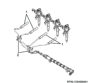
Legend
- Injection pipe
- Clip
3) Temporarily tighten the clip to the injection pipe.
4) Final tighten the injector clamp bolt to the cylinder head.
Tightening torque: 26 N・m { 2.7 kgf・m / 19 lb・ft }
5) Final tighten the injection pipes to the injectors and common rail (fuel rail).
Tightening torque: 44 N・m { 4.5 kgf・m / 32 lb・ft } Injector side
Tightening torque: 44 N・m { 4.5 kgf・m / 32 lb・ft } Common rail (fuel rail) side
6) Securely tighten the clip to the injection pipe.
Tightening torque: 8.0 N・m { 0.8 kgf・m / 71 lb・in }
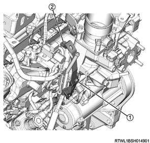
4. EGR cooler bypass control solenoid valve installation
1) Install the EGR cooler bypass control solenoid valve and bracket as a set to the inlet manifold.
Tightening torque: 25 N・m { 2.5 kgf・m / 18 lb・ft }
2) Connect the vacuum hose to the EGR cooler bypass control solenoid valve.
3) Connect the connector to the EGR cooler bypass control solenoid valve.

Legend
- EGR cooler bypass control solenoid valve
5. Swirl control solenoid valve installation
1) Install the swirl control solenoid valve and bracket as a set to the inlet manifold.
Tightening torque: 25 N・m { 2.5 kgf・m / 18 lb・ft }
2) Connect the vacuum hose to swirl control solenoid valve.
3) Connect the connector to swirl control solenoid valve.

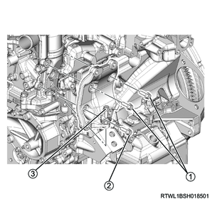
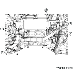
6. Leak-off pipe installation
1) Install the leak-off pipe to the inlet manifold.
Tightening torque: 25 N・m { 2.5 kgf・m / 18 lb・ft }
2) Connect the 2 leak-off hoses to the leak-off pipe.
3) Connect the 3 vacuum hoses to the vacuum pipe.
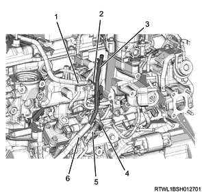
Legend
- Leak-off hose (Injector side)
- Leak-off pipe
- Vacuum pipe
- Vacuum hose (EGR cooler bypass control solenoid valve side)
- Leak-off hose (Supply pump side)
- Vacuum hose (Vacuum pump side)
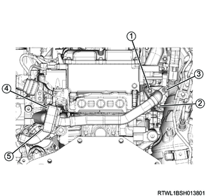
4) Temporarily tighten the harness brackets to the inlet manifold in the order shown in the diagram.
5) Final tighten the harness brackets to the inlet manifold in the order shown in the diagram.
Tightening torque: 10.0 N・m { 1.0 kgf・m / 89 lb・in }
7. A/C compressor bracket installation
1) Temporarily tighten the A/C compressor bracket to the cylinder head.
2) Final tighten the A/C compressor bracket to the cylinder head in the order shown in the diagram.
Tightening torque: 25 N・m { 2.5 kgf・m / 18 lb・ft }
8. A/C compressor connect
1) Connect the A/C compressor to the A/C compressor bracket.
Tightening torque: 51 N・m { 5.2 kgf・m / 38 lb・ft }
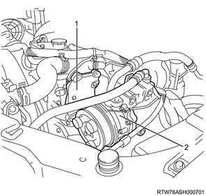
Legend
- A/C compressor bracket
- A/C compressor
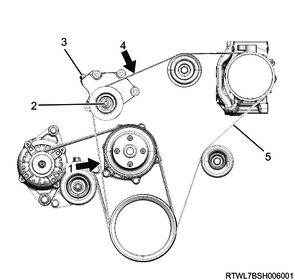
9. A/C compressor drive belt installation
1) Install the A/C compressor drive belt to the following parts.
- Tension pulley
- A/C compressor
- Crankshaft pulley
- Idle pulley
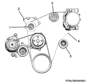
Legend
- Lock nut
- Adjust bolt
- Idle pulley
- A/C compressor drive belt
- Idle pulley
10. Oil level gauge guide tube installation
1) Apply engine oil to the O-ring.
Caution
- Do not reuse the O-ring.
2) Install the oil level gauge guide tube to the crankcase.
Tightening torque: 25 N・m { 2.5 kgf・m / 18 lb・ft }
3) Install the oil level gauge to the oil level gauge guide tube.
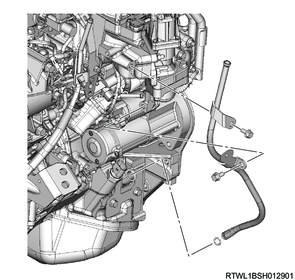
11. EGR cooler bypass pipe installation
1) Temporarily tighten the EGR cooler bypass pipe and gasket to the inlet manifold and exhaust manifold in the order shown in the diagram.
Caution
- Do not reuse the gasket.
- Install the exhaust manifold side gasket with the protrusion facing toward the engine.
Legend
- Protrusion
2) Final tighten the EGR cooler bypass pipe to the inlet manifold and exhaust manifold in the order shown in the diagram.
Tightening torque: 27 N・m { 2.8 kgf・m / 20 lb・ft }
12. Heater pipe connect
1) Temporarily tighten the heater pipe to the inlet manifold in the order shown in the diagram.

2) Final tighten the heater pipe to the inlet manifold in the order shown in the diagram.
Tightening torque: 25 N・m { 2.5 kgf・m / 18 lb・ft }
13. EGR valve installation
14. Boost pressure sensor installation
15. Intake throttle valve installation
16. A/C compressor drive belt adjustment
When installing a new belt, initial stretching of the belt occurs.
In addition, when reusing the belt, the belt needs to be fitted to the pulley groove.
After fitting the A/C compressor drive belt, adjust the tension of the A/C compressor drive belt again.
1) Loosen the tension pulley lock nut.
2) Turn the tension pulley adjust bolt to adjust the tension.
Note
- The standard deflection shown is the value obtained when the specified load is applied to the measurement point of the A/C compressor drive belt.
98 N { 10.0 kg / 22 lb } Load
Caution
- Accurately adjust the tension as there is a possibility the service life of the belt may be shortened or belt squeal may be generated if the tension is not within the appropriate range.
- Use a sonic tension meter to verify accurate tension adjustment.
| Adjustment conditions |
Deflection |
Vibration frequency |
| When new |
10.2 to 11.2 mm { 0.40 to 0.44 in } |
163 to 179 Hz |
| Reused |
12.1 to 13.3 mm { 0.48 to 0.52 in } |
131 to 147 Hz |
| Adjustment conditions |
Deflection |
Vibration frequency |
| When new |
6.8 to 7.4 mm { 0.27 to 0.29 in } |
249 to 273 Hz |
| Reused |
7.9 to 8.7 mm { 0.31 to 0.34 in } |
201 to 225 Hz |
Legend
- Measurement point 1
- Lock nut
- Adjust bolt
- Measurement point 4
- A/C compressor drive belt
3) Tighten the tension pulley lock nut to the specified torque.
Tightening torque: 51 N・m { 5.2 kgf・m / 38 lb・ft }