1. Component views
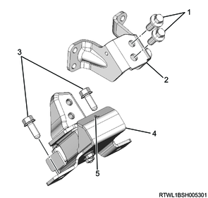
Engine mounting

Part name
- Bolt
- Right side engine foot
- Bolt
- Bolt
- Right side engine mounting
- Bolt
- Left side engine foot
- Bolt
- Bolt
- Left side engine mounting
Tightening torque
1: 131 N・m { 13.4 kgf・m / 97 lb・ft }
3: 51 N・m { 5.2 kgf・m / 38 lb・ft }
4: 116 N・m { 11.8 kgf・m / 86 lb・ft }
6: 131 N・m { 13.4 kgf・m / 97 lb・ft }
8: 51 N・m { 5.2 kgf・m / 38 lb・ft }
9: 116 N・m { 11.8 kgf・m / 86 lb・ft }
2. Preliminary and post procedures
1. Preliminary procedures
1) Open the engine hood.
2) Disconnect the battery cable from the battery negative terminal.
Caution
- After turning OFF the ignition switch (power mode for models with passive entry and start system), do not disconnect the battery cable within 3 minutes.
- If the battery cable is disconnected within 3 minutes, the vehicle electronic control system may malfunction.
- If the battery cable is disconnected, perform the setting of the front door power window switch with AUTO UP/AUTO DOWN function after connecting the battery negative terminal.
3) Raise the vehicle.
3. Underguard removal
4. Engine oil drain
1) Remove the drain plug from the oil pan, and drain the engine oil to a pan.
2) Install the drain plug to the oil pan.
Caution
- Do not reuse the gasket.
- Do not forget to tighten the drain plug.
Tightening torque: 44 N・m { 4.5 kgf・m / 32 lb・ft }
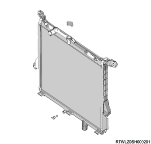
5. Coolant drain
1. Engine coolant drain
Warning
- Do not loosen the radiator cap or reserve tank cap when coolant is hot, as doing so may result in burns caused by the release of steam or hot water.
- When opening the radiator cap, cover the cap with a thick cloth once the engine coolant has cooled and slowly turn to release pressure.
1) Remove the radiator cap from the radiator.
2) Loosen the radiator drain plug, and drain the coolant into a pan.
3) Loosen the drain plug on the cylinder block, and drain the coolant to a pan.
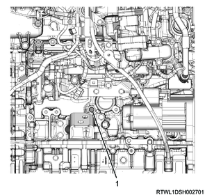
Legend
- Drain plug
4) Apply LOCTITE 262 or equivalent to the threaded portion of the cylinder block side drain plug.
5) Tighten the drain plug on the cylinder block.
Tightening torque: 21.6 N・m { 2.2 kgf・m / 16 lb・ft }
6) Tighten the radiator drain plug.
6. Engine hood removal
7. Wiper linkage removal
8. Cowl panel removal
1) Remove the cowl panel from vehicle.

9. Engine cover removal
1) Remove the engine cover from the engine.

Legend
- Engine cover
10. Air duct removal
1) Remove the intake air duct from the air cleaner and radiator core support.
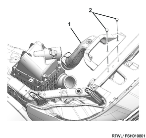
Legend
- Intake air duct
- Clip
2) Remove the PCV hose from the cylinder head cover and air duct.
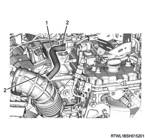
Legend
- PCV hose
- Clamp
3) Remove the air duct from the air cleaner and turbocharger.
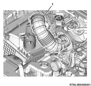
Legend
- Air duct
11. Air cleaner removal
1) Disconnect the connector from the MAF and IAT sensor.
2) Remove the air cleaner from the vehicle.
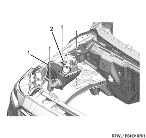
Legend
- Air cleaner
- MAF and IAT sensor
12. A/C compressor drive belt removal
1. M/T models (Euro 5 or above)
1) Loosen the tension pulley lock nut.
2) Loosen the tension pulley adjust bolt.
3) Remove the A/C compressor drive belt from the following parts.
- Tension pulley
- A/C compressor
- Crankshaft pulley
- Idle pulley
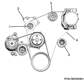
Legend
- Lock nut
- Adjust bolt
- Idle pulley
- A/C compressor drive belt
- Idle pulley
2. Except M/T models (Euro 5 or above)
1) Loosen the tension pulley lock nut.
2) Loosen the tension pulley adjust bolt.
3) Remove the A/C compressor drive belt from the following parts.
- Tension pulley
- A/C compressor
- Crankshaft pulley
Legend
- Lock nut
- Adjust bolt
- A/C compressor drive belt
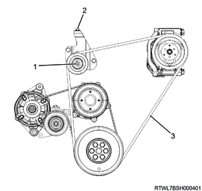
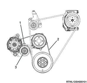
13. Cooling fan belt removal
1) Loosen the tension pulley lock nut.
2) Loosen the tension pulley adjust bolt.
3) Remove the cooling fan belt from the following parts.
- Fan pulley
- Generator
- Crankshaft pulley
MT models

Legend
- Adjust bolt
- Cooling fan belt
- Lock nut
AT models
Legend
- Adjust bolt
- Cooling fan belt
- Lock nut
14. Generator removal
1) Disconnect the B-terminal from the generator.
2) Disconnect the connector from the generator.
3) Remove the upper bracket from the generator and timing gear case.
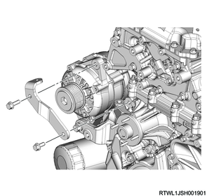
4) Remove the generator from the lower bracket.

15. Exhaust pipe removal
16. Steering shaft disconnect
1) Place alignment marks on the lower second steering shaft.
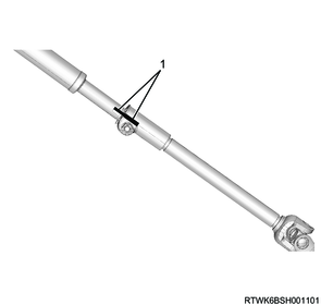
Legend
- Alignment mark
2) Place alignment marks on the universal joint of the lower second steering shaft.
3) Disconnect the universal joint of the lower second steering shaft from the power steering unit.
4) Lock the tilt lever.
5) Remove the lower second steering shaft from the second steering shaft.
Note
- Disconnect the lower second steering shaft at the position shown in the diagram.
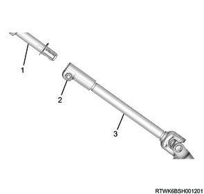
Legend
- Second steering shaft
- Remove the bolt.
- Lower second steering shaft
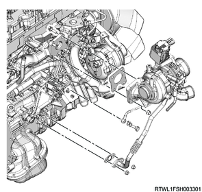
17. DPD removal
1) Remove the heat protector from the turbocharger.

Legend
- Heat protector
2) Remove the V-band from the DPD.
3) Remove the DPD and gasket from the turbocharger.
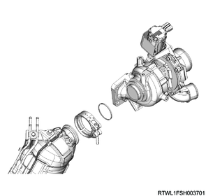
4) Disconnect the differential pressure hose from the DPD.

Legend
- White paint
- Green paint
5) Remove the DPD front upper bracket from the turbocharger upper bracket and DPD.
6) Remove the DPD front lower bracket from the turbocharger lower bracket and DPD.
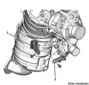
Legend
- DPD front upper bracket
- DPD front lower bracket
7) Remove the DPD rear bracket from the oil cooler side bracket and DPD.
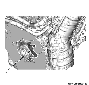
Legend
- DPD rear bracket
8) Remove the exhaust pipe bracket from the crankcase.

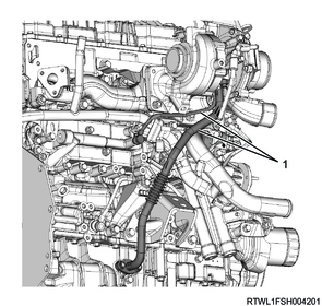
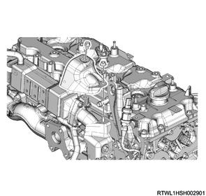
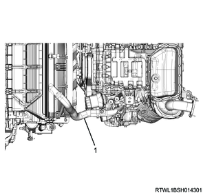
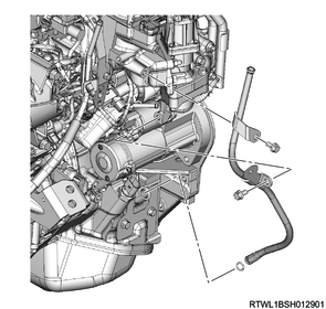
18. Turbocharger water hose disconnect
1) Disconnect the turbocharger water feed hose from the water feed and return pipe.
2) Disconnect the turbocharger water return hose from the water feed and return pipe.

Legend
- Turbocharger water feed hose
- Turbocharger water return hose
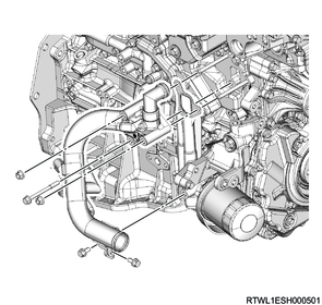
19. Turbocharger oil pipe disconnect
1) Disconnect the turbocharger oil pipe from the oil cooler and crankcase.
Caution
- To prevent the intrusion of foreign material, seal the connections.
- Do not reuse the gasket.
Legend
- Turbocharger oil pipe
20. Turbocharger removal
1) Disconnect the connector from the turbocharger.
2) Remove the following parts as a set from the exhaust manifold.
- Turbocharger
- Turbocharger oil pipe
- Water feed and return pipe
Caution
- To prevent the intrusion of foreign material, seal the connections.
- Do not reuse the gasket.
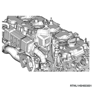
21. EGR cooler water hose disconnect
1) Disconnect the EGR cooler water feed hose from the EGR cooler.
2) Disconnect the EGR cooler water return hose from the EGR cooler.

Legend
- EGR cooler water return hose
- EGR cooler water feed hose
22. EGR cooler removal
1) Remove the upper heat protector from the EGR duct.
2) Remove the lower heat protector from the EGR duct.
3) Remove the harness bracket from the EGR duct.
4) Remove the EGR cooler and gasket from the cylinder head and exhaust manifold.
Caution
- Do not reuse the gasket.
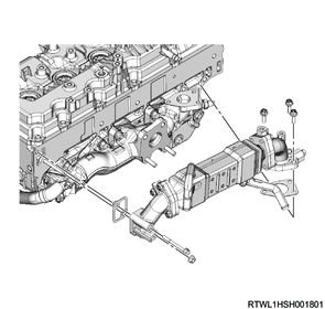
5) Remove the EGR duct and gasket from the EGR cooler.
Caution
- Do not reuse the gasket.

Legend
- EGR duct
- EGR cooler
- EGR duct
23. Radiator lower hose disconnect
1) Disconnect the radiator lower hose from the water intake pipe.
Legend
- Radiator lower hose
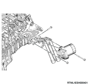
24. Water intake pipe removal
1) Remove the water intake pipe and water hose as a set from the oil filter and oil cooler.
Caution
- Do not reuse the gasket.
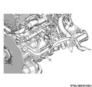
25. EGR water pipe removal
1) Disconnect the water hose from the water intake pipe and return hose.
2) Install the EGR water pipe to the oil cooler and turbocharger lower bracket.
26. Oil filter removal
1) Remove the oil filter and gasket from the oil cooler.
Caution
- Do not reuse the gasket.
27. Oil level gauge guide tube removal
1) Remove the oil level gauge from the oil level gauge guide tube.
2) Remove the oil level gauge guide tube from the crankcase.
Caution
- Do not reuse the O-ring.
28. Front propeller shaft removal
1. 4WD models
Refer to "3.Driveline, Axle 3C.Drive Shaft System front propeller shaft removal".
29. Starter motor removal
1) Disconnect the earth cable from the starter motor.
2) Remove the starter motor from the rear plate.
30. Engine mounting removal
1) Install the special tool to the cylinder head rear side.
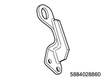
SST: 5-8840-2886-0 - rear engine hanger
Tightening torque: 25 N・m { 2.5 kgf・m / 18 lb・ft }
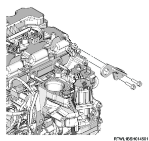
2) Install the wire to the engine hanger and the hoist.
3) Hold up the engine as high as not to be lifted up.
4) Disconnect the right and left engine mountings from the engine foot.
Note
- Loosen the engine mounting fixing bolts from above the engine using an extension bar that is 600 mm {23.6 in} or longer.
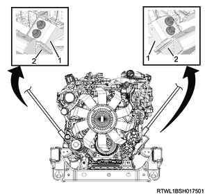
Legend
- Engine foot
- Engine mounting
5) Disconnect the right and left engine feet from the engine.
6) Loosen the mounting bolts between the left side engine mounting and the frame.
Caution
- The right side engine mounting cannot be removed without removing the left side engine mounting.
7) Remove the left side engine mounting and engine foot from the frame.
8) Loosen the mounting bolts between the right side engine mounting and the frame.
9) Remove the mounting bolts between the right side engine mounting and the frame.
Note
- While just slightly hoisting up the engine, perform the work.
Caution
- Perform the work to prevent damage to the engine or vehicle side parts.
10) Remove the right side engine mounting and engine foot from the frame.
Legend
- Engine foot side bolt
- Engine foot
- Engine mounting side bolt
- Engine mounting
- Mark