1. Body control description
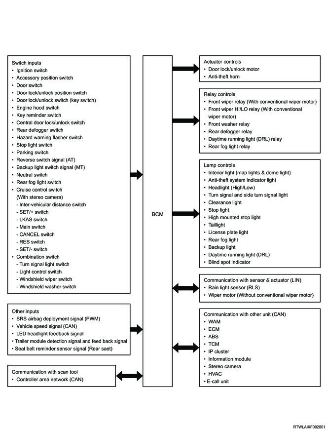
There are 2 versions for the BCM, high version and low version. The BCM is a control module that integrates various vehicle lights, door lock, wiper, and other vehicle electronic controls.
Note
- The BCM indicated with "H" is High version, and that indicated with "L" is Low version.
BCM

Legend
- Label
- BCM Version
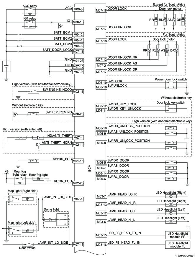
BCM input/output diagram
2. Door lock/unlock control function
The BCM controls the door lock, and it locks/unlocks the doors when it receives the door lock/unlock switch input or the lock/unlock request input from the wireless access module via the CAN communication circuit.
When either one of the lock/unlock signals is detected, the BCM drives the door lock actuator and controls all the doors at the same time.
The door lock/unlock control function has the following detailed functions.
| Door lock/unlock control function |
BCM |
|
| High |
Low |
|
| Central door lock/unlock |
o |
o |
| Door lock/unlock by Remote car lock system |
o |
- |
| Auto door lock |
o |
o |
| Auto door unlock |
o |
o |
| Walk away door lock |
o |
- |
| Impact Sensing Door Unlock |
o |
o |
| Key left prevention unlock |
o |
- |
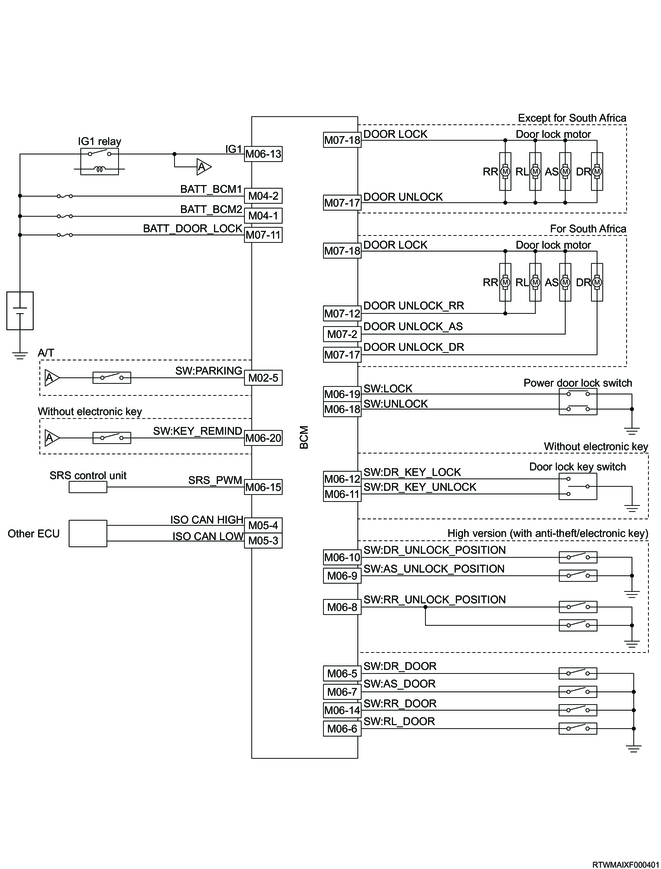
Door lock/unlock control circuit
1. Power door lock/unlock function
<Operating conditions>
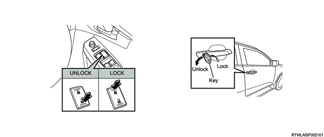
- When the lock/unlock operation of the central door lock switch or door lock key switch is performed, the door lock motor is driven and the doors are locked/unlocked.
<Operation inhibition conditions>
- While any door is open, the lock operation is disabled.
2. Door lock/unlock by Remote car lock system function
When the door lock/unlock request is received from the wireless access module via CAN using the passive entry system function or keyless entry system function, the door lock motor is driven and the door is locked/unlocked.
<Operating conditions>
- The door lock/unlock request is received from the wireless access module via CAN.
<Operation inhibition conditions>
- While any door is open, the lock operation is disabled.
Note
- After doors are unlocked with the passive entry system function or keyless entry system function, if 30 seconds have passed with the doors closed, the re-lock request from the wireless access module is received and the doors are locked.
3. Auto door lock function (Except Australia/New Zealand)
When the BCM meets one of the following conditions, the auto door lock function activates.
1) Speed linked door lock
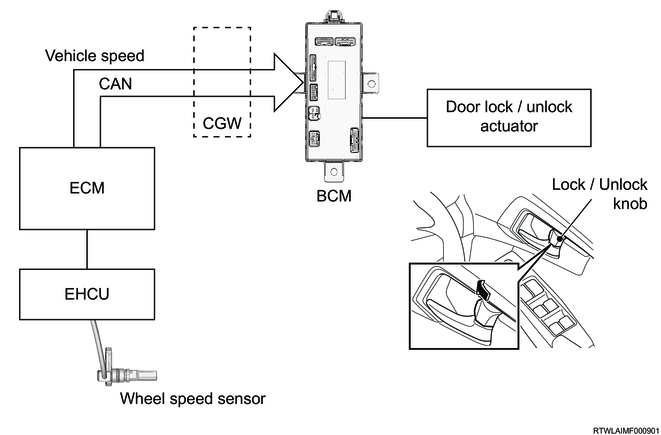
In order to ensure safety, all the doors are automatically locked when the vehicle speed exceeds the set speed even though the doors are not locked by the driver. If the doors are locked by the speed linked door locking, the doors will be automatically unlocked if either the ignition switch is turned OFF or the key is removed after the vehicle has stopped. Also, if any door is unlocked after the door lock by the function, the BCM keeps the door unlocked until the vehicle stops.
Note
- The vehicle speed where the auto door lock activates can be switched between 12 km/h (8 mph) and 20 km/h (13 mph) using the user customization function for models with MID or a scan tool for models without MID. (The default is 20 km/h (13 mph).)
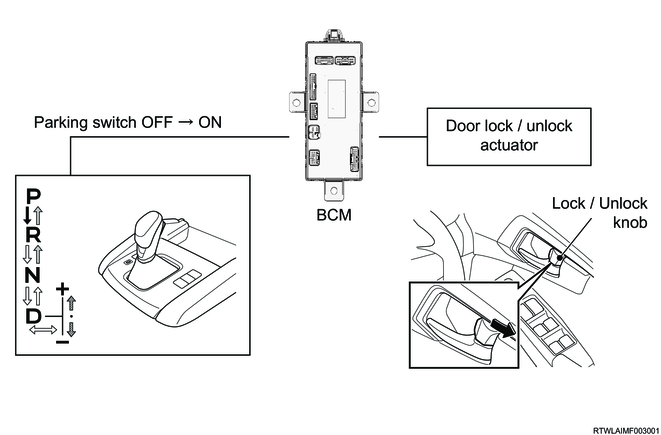
2) Shifter linked door lock (AT only)

When the shift position is changed from the P position to another position, the BCM automatically locks all the doors without the door lock operation by the driver. Also, if any door is unlocked after the door lock by the function, the BCM keeps the door unlocked until the vehicle stops.
Note
- The auto door lock function can be changed to either one of the above 2 cases or can be disabled using the user customization function for models with MID or a scan tool for models without MID. (The default is speed linked door lock.)
- Whether or not the door lock is performed again when the doors are opened and closed after the auto door lock is operated in the above 2 cases can be set by selecting Enable/Disable of the auto lock enable door using the user customization function for models with MID or a scan tool for models without MID. (The default is Enable.)
4. Auto door unlock function (Except South Africa)
When the BCM meets one of the following conditions, the auto door unlock function activates.
1) Shifter linked door unlock (AT only)
When the shift position is changed to the P position even while the door lock is in operation, the BCM automatically unlocks all the doors.
2) Ignition linked door unlock
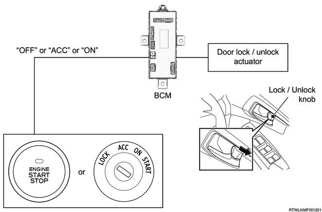
When the power mode of the engine start/stop button is set from ACC or ON to OFF (models with passive entry and start system) or the ignition switch is set from ACC or ON to OFF (except models with passive entry and start system), the BCM automatically unlocks all the doors.
3) Key Linked Door Unlock (Except models with passive entry and start system)

When the key is pulled out from the ignition switch even while the door lock is operating, the BCM automatically unlocks all the doors.
Note
- The auto door unlock function can be changed to either one of the above 3 cases or can be disabled using the user customization function for models with MID or a scan tool for models without MID.
- The default is Ignition linked door unlock (Models with passive entry and start system) or Key Linked Door Unlock (except models with passive entry and start system).
5. Walk away door lock function
For the walk away door lock, if the driver left the vehicle with carrying the electronic key and walked away a certain distance without locking the doors, the wireless access module (Hi-version) sends the locking request to the BCM. When the BCM receives the locking request, it drives the door lock motor and locks the doors.
Note
- For the details of the function, refer to the security lock control chapter.
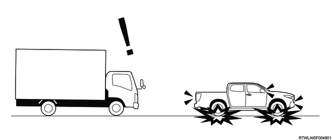
6. Impact Sensing Door Unlock function
If the SRS airbag is deployed, the door lock is automatically released based on the deployment signal sent from the SRS control unit. At this time, the hazard warning flasher is flashed to notify the surrounding about the danger.
7. Key left prevention unlock function
When the key left prevention unlock operating conditions are met, the BCM unlocks all the doors to prevent the driver from leaving the key in the vehicle.
<Key left prevention unlock operating conditions>
- When the wireless access module detects that the doors have been locked while the electronic key is in the vehicle cabin, it sends the unlock request to the BCM via the CAN communication circuit. (Models with passive entry and start system)
- The BCM detects that the doors are locked with the key inserted into the ignition switch. (Models without passive entry and start system)
Note
- For models not equipped with passive entry and start system, the key left prevention unlock function can be activated only when the vehicle is equipped with the anti-theft system.
8. Selective unlock function (For South Africa)
The selective unlock function is a function that unlocks the doors and tailgate in steps depending on the number of times the driver performs an unlocking operation from outside the vehicle. Only the driver-side door is unlocked by the first unlock operation. If the second unlocking operation is performed within 3 seconds after the first unlocking operation, all the doors other than the driver-side door and tailgate are unlocked.
<Operating conditions>
- All the doors and tailgate are locked.
- The doors are unlocked by the unlock button of the electronic key or the request switch on the outside handle (models with passive entry and start system).
- The doors are unlocked by the unlock button of the keyless entry key (for models with Keyless entry system).
Note
- For the details of the function, refer to the security lock control chapter.
3. Anti-theft function
The anti-theft system consists of the BCM, anti theft horn, anti-theft system indicator light, wireless access module, and electronic key or keyless entry key, and it is designed to protect the vehicle and valuables from theft. It is activated when all the doors and the engine hood are closed and the doors are locked using a properly-programmed electronic key or keyless entry key, and deactivated when the doors are unlocked or the ignition switch is turned ON.
If someone attempts to open a door or the engine hood forcibly without using the electronic key or keyless entry key, it will activate the anti-theft system alarm.
The alarm sounds the horn and flashes the hazard warning flasher, and the horn continues to sound for 30 seconds and the hazard warning flasher continues to flash for 5 minutes until automatically stopped by the system.
Caution
- In order to activate the anti-theft system, close all the doors and then lock the doors using the electronic key or keyless entry key.
- When the door at the passenger side is opened in locked status and then the door is closed, an error alert is detected.
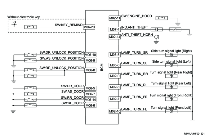
Anti-theft system control circuit
| Time since door locking with electronic key or keyless entry key |
Anti theft indicator light |
Anti-theft system |
| The first 10 seconds |
Illuminated |
System: in preparation |
| Rapid flashing (2 Hz) |
The doors or engine hood is open, or there is a system failure. |
|
| After approx. 10 seconds |
Slow flashing (0.5 Hz) |
System: ON |
| OFF |
System: OFF |
<System operation>
Turn OFF the ignition switch.
Check that all the doors and engine hood are closed, and then lock the doors with the electronic key or keyless entry key.
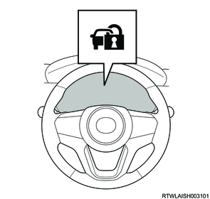
If the anti-theft system indicator light illuminates for approximately 10 seconds and starts flashing slowly afterwards, the anti-theft system will operate.
<Anti-theft system alarm operating conditions>
- Someone attempts to forcibly open a door or the engine hood without using the electronic key or keyless entry key.
- A door is unlocked using the door lock knob.
- The engine hood lock control lever is operated.
- The driver attempts to turn ON the ignition switch when the electronic key is not authenticated by the wireless access module. (Models with passive entry and start system)
- The key is inserted into the ignition switch. (Models without passive entry and start system)
<Anti-theft system stop conditions>
- The doors are unlocked with the electronic key or keyless entry key, or the ignition switch is turned ON.
Note
- If the anti-theft system alarm operates, it will be disabled when the ignition switch is turned ON or when the lock/unlock button of the electronic key or keyless entry key is operated.
4. Exterior light control function
When the BCM detects any input of the light control switch, it illuminates the exterior light according to the driver's operations.
The exterior light control function has the following detailed functions.
| Exterior light control function |
BCM |
|
| High |
Low |
|
| Manual head light |
o |
o |
| Auto head light |
o |
- |
| Automatic high beam |
o |
- |
| Headlight battery saver |
o |
o |
| Coming home light |
o |
o |
| Stop light |
o |
o |
| Tail light & clearance light |
o |
o |
| Rear fog light |
o |
o |
| Backup light |
o |
o |
| Daytime running light |
o |
o |
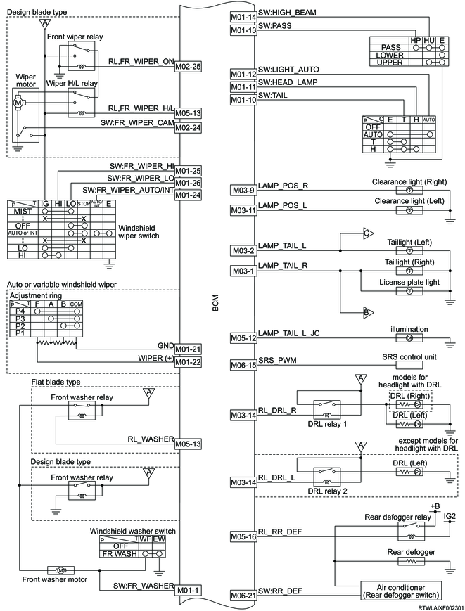
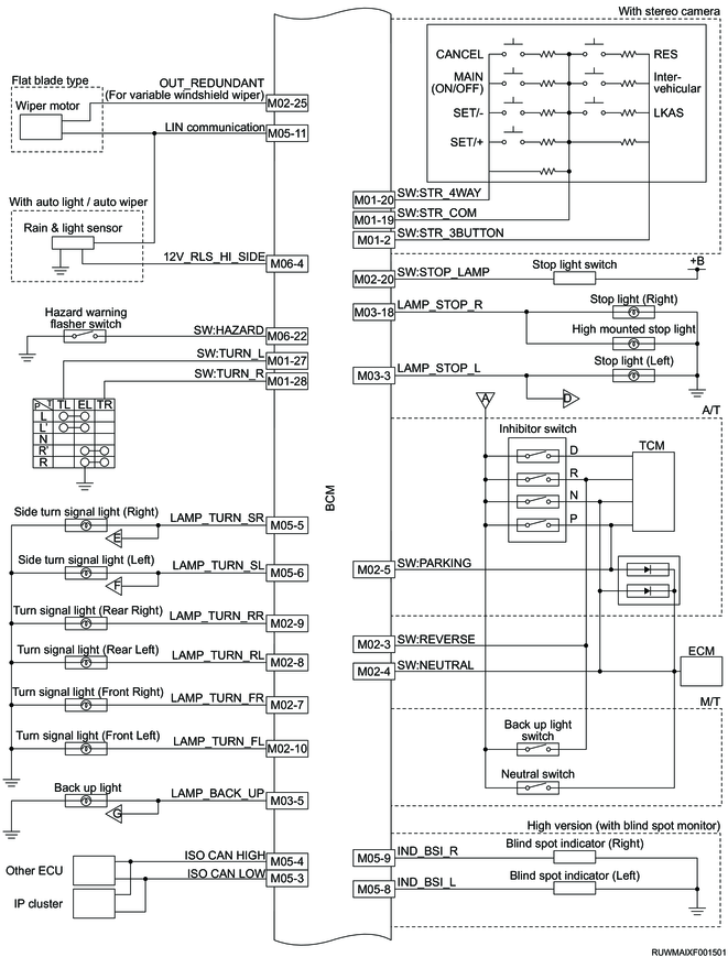
Exterior light control circuit

1. Manual head light control function
The light control switch and high beam switch signals are input to the BCM. The BCM controls the headlight based on the input signals as shown in the following.
| BCM input |
BCM output |
|
| Light control switch |
High beam switch |
Illuminate control |
| OFF |
- |
- |
| TAIL |
- |
CLEARANCE/TAIL |
| LO |
OFF |
LOW BEAM |
| ON |
HIGH BEAM |
|
2. Auto head light control function (Models with rain and light sensor)
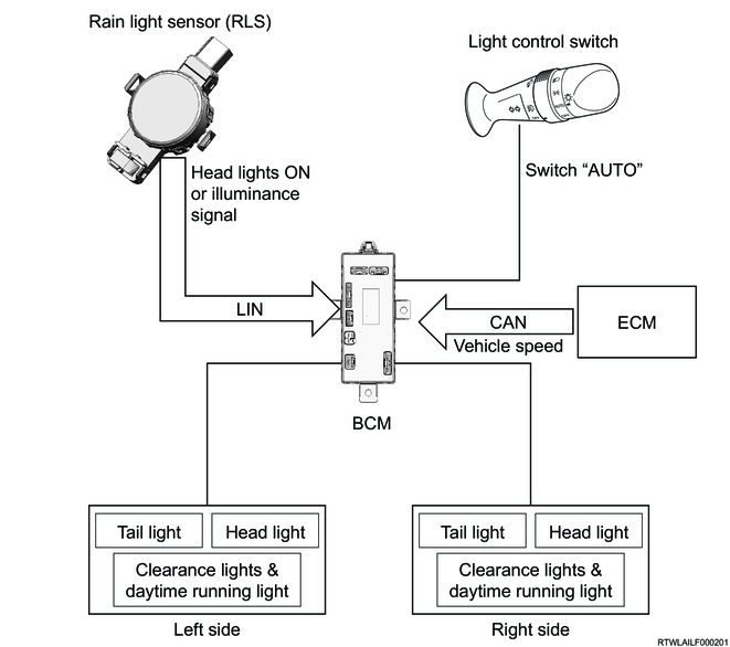
The BCM receives the illuminance signal and head light illumination request from the rain and light sensor (RLS) via the LIN communication circuit. When the light control switch is in the AUTO position, the BCM illuminates the following lights according to the illuminance signal and head light illumination request that are received from the RLS.
- Clearance light/tail light/license plate light
- Head light (low beam)
Note
- When the BCM detects an RLS malfunction while the light control switch is set to the AUTO position, the head light (low beam) always illuminates regardless of the brightness outside the vehicle.
- For models with MID, the auto light sensitivity can be adjusted with the user customization function.
3. Automatic high beam control function (Models with stereo camera)
The automatic high beam (AHB) control function is a function to detect taillights of the vehicle ahead or the headlights of the oncoming vehicle during night driving and to switch the headlight illumination level (low/high beam) automatically according to the surrounding traffic conditions. When the high beam switch is in the ON position and the headlights are illuminated by the auto headlight control function, the BCM switches the headlight illumination level (low/high beam) automatically according to the auto high beam request received from the stereo camera via the CAN communication circuit.
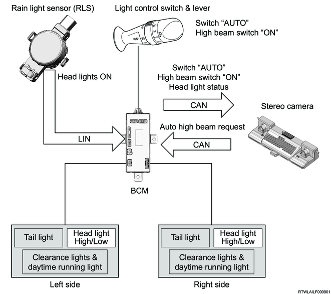
<Automatic high beam control function operating preconditions>
- The light control switch is in the AUTO position. (The headlight illuminates.)
- The high beam switch is in the ON position.
<Automatic high beam control function operating conditions>
- The auto high beam request is received from the stereo camera.
Note
- For the details of function, refer to the Driver Assistance System (stereo camera) chapter.
4. Headlight battery saver function

When a specific condition is met, the BCM automatically turns OFF the headlight to prevent the battery drain. If any of the following is met while the ignition switch is OFF and the light is illuminating (the light control switch is in the TAIL or LO position), it turns OFF automatically.
If any of the following is met while the ignition switch is OFF and the lights are illuminating (the light control switch is in the TAIL or LO position), they turn OFF automatically.
- The driver side door is opened.
- The doors are locked with the passive entry and start system function or keyless entry system function from outside the vehicle.
Note
- While the headlights are illuminated by the coming home light function, this function does not turn OFF the light.
- Enable/Disable can be selected using the user customization function for models with MID or a scan tool for models without MID. (The default is Enable.)
5. Coming home light function
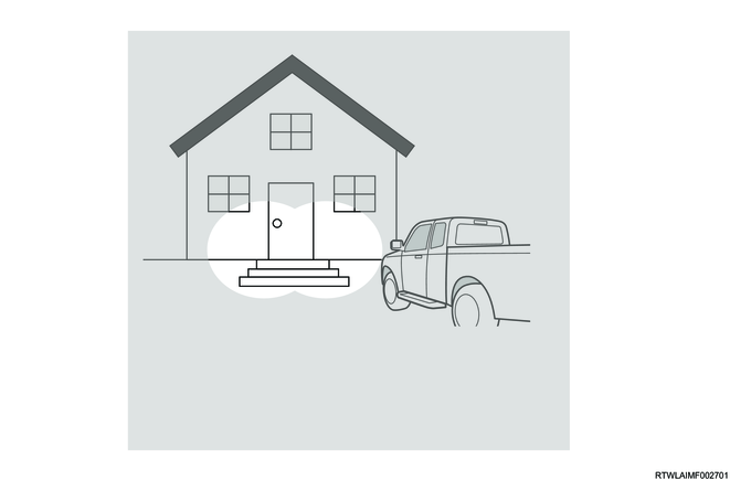
Coming home light is a function that illuminates the head light (low beam) and clearance light for 30 seconds according to a specific operation. When moving the light control switch lever to the passing position while the ignition switch is OFF and the light control switch is in the OFF or AUTO position, the head light (low beam) and clearance light illuminate for approximately 30 seconds. When the light illuminates, the light position indicator light in the instrument panel cluster illuminates.
When any of the following is operated while the light is illuminated by the function, the BCM turns OFF the light.
- Move the light control switch lever to the passing position again.
- Turn ON the ignition switch.
Note
- Enable/Disable can be selected using the user customization function for models with MID or a scan tool for models without MID. (The default is Enable.)
- The illuminating time can be changed to 30 seconds, 60 seconds, or 120 seconds with a scan tool. (The default is 30 seconds.)
6. Stop light control function
When the stop light switch ON signal is input to the BCM by the driver's brake operation, the BCM illuminates the stop light and high mounted stop light. Also, it illuminates the lights when receiving a stop light illumination request from the EHCU via the CAN communication circuit during AEB or ESC operation, etc.
7. Taillight & clearance light control function
When the taillight switch ON signal is input to the BCM by the driver's light control switch operation, the BCM illuminates the clearance light and taillight. The license plate light is also illuminated by the BCM taillight output. Also, it performs the output of the tail junction (illumination) circuit according to the taillight output and illuminates the related components (audio, switch, etc.). Also, it supplies power to the front fog relay based on the output of the tail junction (illumination) circuit.
8. Rear fog light control function
When the rear fog light switch ON signal is input to the BCM by driver's fog light switch operation while the headlights are illuminated, the BCM turns ON the rear fog light relay output and illuminates the rear fog light. When the rear fog light is illuminated, the rear fog light indicator in the instrument panel cluster is illuminated. When the BCM detects the clearance light OFF or the rear fog light switch ON signal input again, it turns OFF the rear fog light relay output, and then turns OFF the rear fog light.
<Preconditions>
- The ignition switch is ON.
- The light control switch is in the AUTO or LO position. (The headlight illuminates.)
<Illumination conditions>
- Rear fog light switch is shifted to the ON position.
<Light OFF conditions>
- The rear fog light switch is shifted to the ON position again.
- The clearance light or ignition switch is turned OFF.
9. Backup light control function
When the gear is shifted into the "R" position by the driver's shift operation, the backup light switch ON signal is input to the BCM, and then the BCM illuminates the tail light and back up light.
10. Daytime running light control function
The BCM controls the turning ON and OFF of the daytime running light (DRL). The BCM turns ON the DRL when it detects that all the illumination conditions are met. BCM turns OFF the DRL while the headlights or front fog lights are illuminated. When it detects that the headlights or front fog lights are turned OFF, the DRL is turned ON again. Also, when it detects that the ignition switch is turned OFF, the DRL is turned OFF.
<Illumination conditions>
- The ignition switch is ON.
- The light control switch is in the OFF, TAIL, or AUTO position. (The headlight does not illuminate.)
- The parking brake is released.
- The selector lever is in a position other than the P position (AT model only).
<Light OFF conditions>
- The light control switch is in the LO or AUTO position. (The headlights are illuminated.)
- The front fog light is illuminated.
- Turn signal light is in operation (except models for headlight with DRL).
- The ignition switch is OFF.
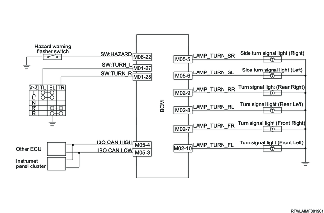
5. Flasher control function
When the BCM detects a turn signal switch input, it flashes the left or right turn signal light based on the switch input. When an input from the hazard warning flasher switch, etc. is detected, all the turn signal lights are flashed (hazard warning flasher). The instrument panel cluster sounds the turn signal chime. The turn signal chime requests are output to the instrument panel cluster from the BCM via the CAN communication circuit.
The turn signal light/hazard warning flasher control function has the following detailed functions.
| Flasher control function |
BCM |
|
| High |
Low |
|
| Turn signal light |
o |
o |
| Comfort turn signal light |
o |
o |
| Hazard warning flasher |
o |
o |
| Emergency Stop Signal (ESS) |
o |
o |
| Answerback |
o |
- |
Flasher control circuit
1. Comfort turn signal light control function

The function is to flash the turn signal light 3 times. When the light control switch lever is slightly moved up or down and released, the turn signal light flashes 3 times. To turn OFF the flashing turn signal light, slightly move up or down the lever again.
Note
- Enable/Disable can be switched using the user customization function for models with MID or a scan tool for models without MID. (The default is Enable.)
2. Hazard warning flasher control function

When one of the following situations is met, the BCM operates the hazard warning flasher.
- The hazard warning flasher switch is pressed.
- The anti-theft system operates.
- The doors are locked/unlocked by the remote car lock system (answerback control).
- The SRS airbag deployment signal is received.
- The emergency stop signal (ESS) is received.
3. Emergency Stop Signal function
When a sudden braking is applied while the vehicle is driving at approximately 60 km/h (37.5 mph) or more, the function alerts a following vehicle that there is a possibility of a collision by flashing the hazard warning flasher automatically and rapidly. While the function is in operation, both turn signal indicator lights in the instrument panel cluster flash.
Under the following conditions, the ESS stops operating and the hazard warning flasher turns OFF.
- Sudden deceleration is stopped.
- The brake pedal is released.
- The ABS is stopped.
- The hazard warning flasher switch is pressed.
Note
- When the hazard warning flasher switch is pressed and the hazard warning flasher flashes, the ESS does not operate.
4. Answerback control function
When requests are received from the wireless access module with the keyless entry system or passive entry and start system and the doors are locked/unlocked, the hazard warning flasher flashes the predetermined number of times.
- Once when the doors are locked
- Twice when the doors are unlocked
6. Interior light control function
The BCM drives the interior (dome) light.
The interior light control function has the following detailed functions.
| Interior light control function |
BCM |
|
| High |
Low |
|
| Interior light |
o |
o |
| Welcome light |
o |
- |
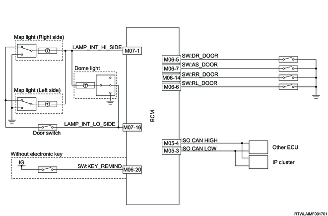
1. Interior light control
When any of the following is met while the dome light switch is in the DOOR position, the dome light and map light are illuminated or turned OFF.
<Illumination conditions>
- The key is pulled out from the ignition switch.
- Any door is open.
- All the doors are unlocked.
- There is the welcome light request from the wireless access module (illumination for 30 seconds).
<Light OFF conditions>
- The key is inserted into the ignition switch, and then all the doors are closed.
- All the doors are closed, and then the ignition switch is turned ON.
- All the doors are closed and locked with the keyless entry system or passive entry and start system.
Note
- If the ignition switch is OFF and the doors are opened, closing the doors illuminates the light, and then it turns OFF after approximately 30 seconds.
- Whether the dome light and map light illuminate when the doors are unlocked by the remote car lock system function can be set with Enable/Disable of the interior light linked RKE on the user customization function for models with MID or on the scan tool for models without MID. (The default is Enable.)

The BCM controls the dome light and map light via the high side drive circuit and low side drive circuit. The light fade-off control is performed via the low side drive circuit. Also, the high side drive circuit is almost always energized. 10 minutes after the dome light and/or map light illuminates with the ignition switch OFF and with all the doors closed, the BCM automatically shuts off the high side drive circuit to prevent the battery discharge.
2. Welcome light function
For the welcome light function, when the wireless access module (Hi-version) detects that the driver carrying the electronic key approaches the vehicle, it sends the welcome light request to the BCM. When the BCM receives the welcome light request, it illuminates the dome light and map light for 30 seconds.
Note
- For the details of the function, refer to the security lock control chapter.
7. Wiper, washer control function
When the windshield wiper switch signal or windshield washer switch signal is input, the BCM controls the wiper motor. Depending on the equipped wiper motor, the control method by the BCM differs. The wiper and washer controls have the following functions.
| Wiper/washer control function |
BCM |
|
| High |
Low |
|
| Manual wiper |
○ |
○ |
| Automatic wiper |
○ |
- |
| Washer |
○ |
○ |
Wiper and washer control circuit
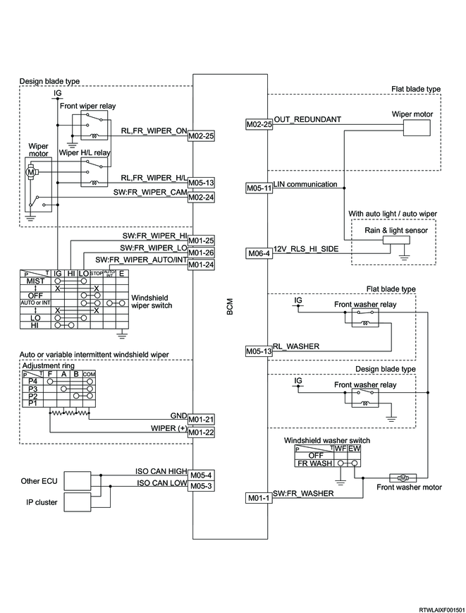
1. Design blade type (BCM control type: Direct)
- Washer linked function
- Manual wiper (INT drive function)
- Manual wiper (LO [low speed] drive function)
- Manual wiper (HI [high speed] drive function)
1) Washer linked function
The function is to link the wiper operation when the washer is operated. When the BCM detects the windshield washer switch signal, the wiper motor is driven at a low speed shortly after the washer motor operates.
2) Manual wiper (INT drive function)
The function is to operate the wiper intermittently. When the windshield wiper switch is set to the INT (intermittent) position, the BCM drives the wiper motor at a low speed for only a predetermined period of time at predetermined intervals.
The intermittent time for models with variable intermittent windshield wipers can be adjusted by operating the adjustment ring. Also, the BCM receives a vehicle speed signal from the ECM via the CAN communication circuit. The BCM automatically adjusts the intermittent time according to the vehicle speed based on the received vehicle speed signal.
3) Manual wiper (LO [low speed] drive function)
The function is to operate the wiper at a low speed. When the windshield wiper switch is set to the LO (low speed) position, the BCM turns the front wiper relay ON and the wiper H/L relay OFF and switches the wiper motor drive circuit to the LO side to drive the wiper motor at a low speed.
4) Manual wiper (HI [high speed] drive function)
The function is to operate the wiper at a high speed. When the windshield wiper switch is set to the HI (high speed) position, the BCM turns ON the front wiper relay and wiper H/L relay and switches the wiper motor drive circuit to the HI side to drive the wiper motor at a high speed.
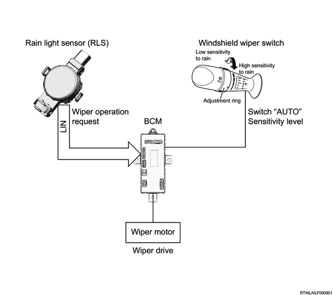
2. Flat blade type (BCM control type: LIN communication)

- Washer linked function (Washer motor power supply cut function)
- Manual wiper function
1) Washer linked function (Washer motor power supply cut function)
When the BCM detects that the windshield washer switch is ON, it sends the low speed drive request to the wiper motor. The washer nozzle for the flat blade equipped models is built into the wiper arm. The BCM receives the wiper position angle signal from the wiper motor via the LIN communication circuit. When the wiper arm (washer nozzle) is outside the predetermined range of the angles for washer injection, the BCM controls the washer relay and temporarily cuts the power supply to the washer motor to restrict the washer injection.
2) Manual wiper function
The BCM detects the windshield wiper switch signals. The BCM sends the wiper operation request according to the switch operation to the wiper motor via the LIN communication circuit. The wiper motor controls the wiper according to the wiper operation request received from the BCM.
Note
- The INT operates as a variable intermittent windshield wiper.
- If the BCM detects a malfunction in the wiper motor, it controls the redundant circuit and activates the wiper motor as the variable intermittent wiper.
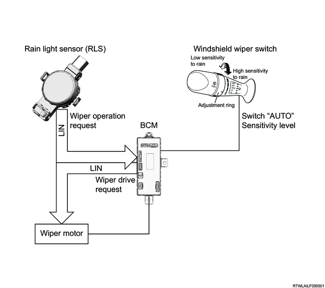
3. Automatic wiper function (Models with rain and light sensors)
Design blade type
Flat blade type
| Rainfall |
Wiper state |
| No rain |
Stopped |
| Light rain |
Intermittent |
| Moderate rain |
Low speed |
| Heavy rain |
High speed |
The automatic wiper function is a function that automatically wipes the windshield according to the amount of rainfall. The rain and light sensor (RLS) sends the wiper operation request determined from the raindrop amount to the BCM via the LIN communication circuit. When the following conditions are met, the BCM performs the wiper operation according to the request from the RLS.
- The windshield wiper switch is in the AUTO position.
- Error messages are not received from the RLS or wiper motor (flat blade type).
- The LIN communication circuit is normal.
- The automatic wiper function is set to Enable.
Also, adjusting the adjustment ring of the windshield wiper switch can change the raindrop detection sensitivity of the RLS. The BCM sends a raindrop detection sensitivity signal to the RLS via the LIN communication circuit.
When the windshield wiper switch is set to the AUTO position while any of the following conditions is met, the BCM operates the wiper motor as a variable intermittent windshield wiper.
- An RLS malfunction is detected by the BCM.
- The automatic wiper function is set to Disable with a scan tool or the user customization function of the instrument panel cluster.
Note
- When the BCM detects an RLS malfunction while the function is operating, the continuous wiper operation is performed with the wiper request received before the malfunction is detected until the ignition switch is turned OFF or the windshield wiper switch is operated from the AUTO position.
1) Splash wiping function
When a rapid increase of raindrops on the windshield due to passing oncoming vehicle , etc., is detected during the automatic wiper function operation, the splash wiping function cancels the automatic wiper operation and drives the wipers at a high speed to wipe off the raindrops. When the RLS detects a rapid increase of the raindrops, it sends the splash wiping request to the BCM. The BCM sends the received splash wiping request to the wiper motor.
The BCM finishes the splash wiping function under the following conditions.
- There is no splash wiping request from the RLS. (The automatic wiper function is resumed.)
- The windshield wiper switch is changed from the AUTO position.
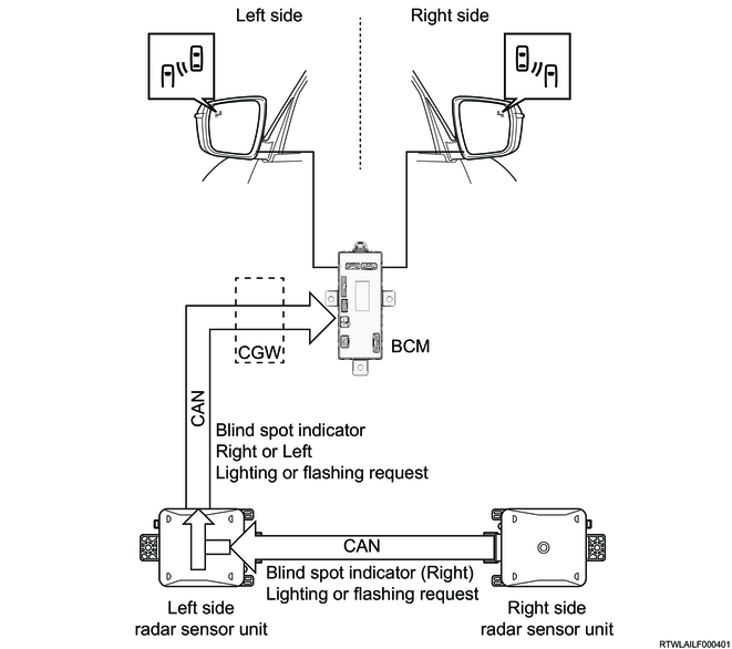
8. Blind spot indicator function
<High version only>
The BCM receives the control information from the right and left radar sensor units via the CAN communication circuit.
When the BCM receives the lighting or flashing request of the blind spot indicator from either right or left radar sensor unit, the BCM illuminates or flashes the blind spot indicator on the requested side using the PWM control.
Also, when the illumination conditions for the clearance light are met, the BCM reduces the brightness of the blind spot indicator.
9. Rear defogger control function
When the rear defogger switch is pressed while the ignition switch is ON, the rear defogger relay is driven, the indicator light illuminates, and then the rear defogger activates. When the rear defogger switch is pressed again, the function is deactivated. In addition, even when the rear defogger switch is ON, the function is automatically disabled after operating for approx. 10 minutes.
Rear defogger control circuit
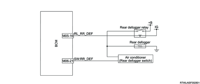
When the BCM detects the rear defogger switch signal, it controls the rear defogger relay.
Depending on the equipped air conditioner system, a part of the rear defogger control differs as shown in the following.
- The rear defogger relay of models with automatic A/C supplies the voltage to the rear window defogger.
- The rear defogger relay of models with cooler/heater/manual air conditioner supplies the voltage to the rear window defogger and switch indicator.
When the rear defogger switch is pressed again, the BCM turns OFF the rear defogger relay.
If the rear defogger switch remains ON, the BCM turns OFF the rear defogger relay after 10 minutes.
10. Customize function
The BCM functions can be changed as shown in the following with the user customization function for models with MID or a scan tool for models without MID.
| Function |
Display titles of the setting items |
The details of the function |
Display titles of the options |
Option details |
Default |
| Door lock |
Auto unlock type |
Setting of the timing where the door lock is released (Modes with passive entry and start system) |
Disable |
The auto unlock is disabled. |
|
| IGN |
The lock is released when the power mode is turned OFF. |
O |
|||
| Shift-P |
The lock is released when the selector lever is set to the P position (AT only). |
||||
| Auto unlock type |
Setting of the timing where the door lock is released (Except models with passive entry and start system) |
Disable |
The auto unlock is disabled. |
||
| KEY |
The lock is released when the key is removed. |
O |
|||
| IGN |
The lock is released when the ignition switch is turned OFF. |
||||
| Shift-P |
The lock is released when the selector lever is set to the P position (AT only). |
||||
| Auto lock enable by door |
A function to set the conditions for reactivating the auto lock function by the door opening/closing (Models with keyless entry system or passive entry and start system and SRS airbag system) [Except Australia/New Zealand] |
Enable |
Even when the doors are opened then closed, the auto lock is performed again. |
O |
|
| Disable |
Once the auto lock is performed, it does not operate after the doors are opened/closed. (When the ignition switch is turned from OFF to ON, the auto lock operates again.) |
||||
| Auto lock speed |
Setting of the vehicle speed where the auto door lock activates (Models with keyless entry system or passive entry and start system and SRS airbag system) [Except Australia/New Zealand] |
20 km/h (13 mph) |
It activates when the vehicle speed becomes 20 km/h (13 mph) or more while Speed is set. |
O |
|
| 12 km/h (8 mph) |
It activates when the vehicle speed becomes 12 km/h (8 mph) or more while Speed is set. |
||||
| Auto lock type |
Setting of the conditions for activating the auto door lock (Models with keyless entry system or passive entry and start system and SRS airbag system) [Except Australia/New Zealand] |
Disable |
The auto door lock function is disabled. |
||
| Speed |
The auto door lock operates when the vehicle speed reaches the set speed. |
O |
|||
| Except Shift-P |
The auto door lock operates when the selector lever is in a position other than the P position. |
||||
| LIGHT |
Auto light sensitivity |
Adjustment of the auto light sensitivity (Models with auto head light) |
0 |
The sensitivity is low. (The light illumination timing is slow and OFF timing is rapid.) |
O |
| 1 |
↓ |
||||
| 2 |
↓ |
||||
| 3 |
The sensitivity is high. (The light illumination timing is rapid and OFF timing is slow.) |
||||
| Headlight battery saver |
Battery saver function for the case that the headlight is ON with the ignition switch OFF |
Enable |
Battery saver function ON (When the driver side door is opened, it turns OFF.) |
O |
|
| Disable |
The battery saver function is OFF. |
||||
| Coming home light |
A function to illuminate the headlight for 30 seconds to light up the way to entrance when flashing the headlights with the ignition switch OFF |
Enable |
The function is ON. |
O |
|
| Disable |
The function is OFF. |
||||
| Comfort turn signal |
A function to flash the turn signal indicator and turn signal light 3 times when the turn signal lever is slightly moved to the left (or right) and released. |
Enable |
ON |
O |
|
| Disable |
OFF |
||||
| Interior light linked RKE |
A function to link the interior light (dome light) with the keyless entry (Models with keyless entry system or passive entry and start system) |
Enable |
The link is ON. |
O |
|
| Disable |
The link is OFF. |
||||
| WIPER |
Automatic wiper |
Auto wiper function (Models with automatic wiper) |
Enable |
The auto wiper is ON. |
O |
| Disable |
The auto wiper is OFF. |
Note
- The illuminating time of the coming home light can be changed to 30 seconds, 60 seconds, or 120 seconds with a scan tool.
11. Diagnostic function
A self-diagnosis function to determine diagnose areas, backup function, and DTCs corresponding to the diagnose areas are set in the BCM. If the function is not operating correctly, the DTC is set.
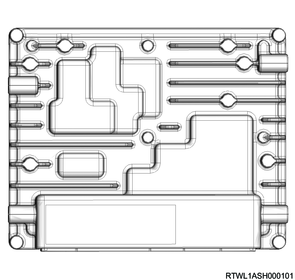
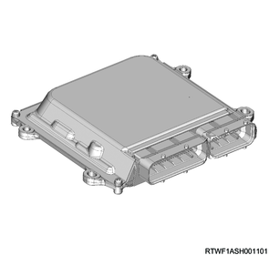
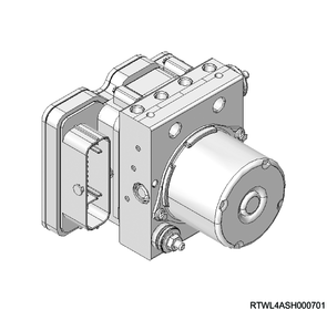
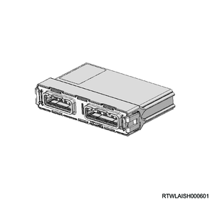
12. Body controls components
1. BCM
The BCM has the following functions.
- Door lock/unlock control function
- Anti-theft function
- Exterior light control function
- Flasher control function
- Interior light control function
- Wiper and washer control function
- Blind spot indicator function
- Rear defogger control function
- Self-diagnosis function
The BCM sends to and receives from other control units the information required for control via the CAN communication circuit. The BCM is installed to the driver side dash side panel.
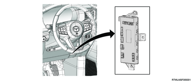
Note
- The illustration shows an RHD model.
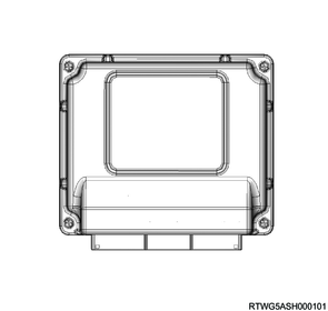
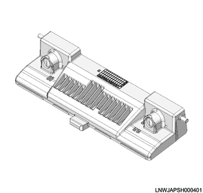
2. Rain and light sensor
The rain and light sensor (RLS) is installed to the cabin side of the windshield, and the sensor has the rain sensor function and light sensor function.
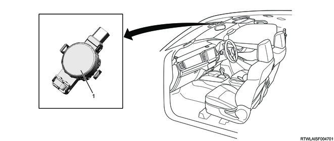
Legend
- Rain and light sensor
The rain sensor detects raindrops on the windshield, and it is used for the automatic wiper function. The wiper operation request corresponding to the detected raindrops is sent to the BCM via LIN communication.
The light sensor detects the brightness outside the vehicle, and it is used for the auto head light function. The detected brightness outside the vehicle (illuminance signal) and head light ON/OFF request are sent to the BCM via LIN communication.
The RLS has a self-diagnosis function, and if it detects a malfunction, the error information is sent to the BCM via LIN communication.
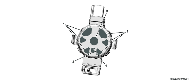
Legend
- LED
- Light sensor (AL)
- Rain sensor Light sensor (IR)
- Light sensor (FW)
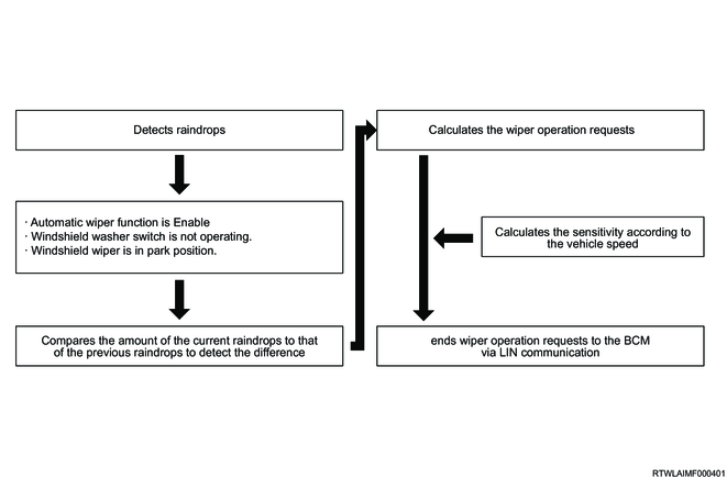
1) Rain sensor function
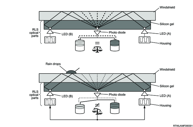
The rain sensor operates in the wavelength range of the infrared rays. Whether there are any raindrops or not is determined by illuminating the LED (A) and LED (B) of the sensor and by detecting raindrops with the photo diode (Receiver).
The infrared rays emitted from the LED are reflected by the windshield and enter the photo diode. When there are raindrops on the windshield, the amount of the infrared rays entering the photo diode is decreased because the infrared rays penetrate the windshield through the raindrops on the windshield and reach the outside of the vehicle. As the amount of raindrops increases, the amount of infrared rays entering the photo diode decreases.
The following diagram shows the determination flow of the wiper speed.
2) Light sensor function
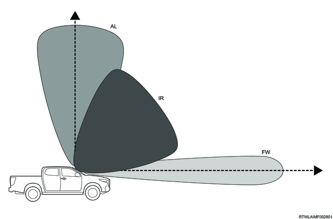
The light sensor operates in the wavelength ranges of visible lights and infrared rays. The light outside the vehicle is detected by 3 photo diodes (FW/IR/AL) on the sensor. The 3 photo diodes measure independently of each other.
Diode FW (ForWard): This is used to measure the light in the moving direction of the vehicle. This photo diode reacts with visible light.
Diode IR (Infra Red): This is used to measure the ambient light perpendicularly directing to the vehicle windshield. This photo diode reacts with infrared light.
Diode AL (Ambient Light): This is used to measure the ambient light above the vehicle. This photo diode reacts with visible light.
The relations between the head light and each diode are as follows.
| Situation |
Head light |
Diode AL |
Diode IR |
Diode FW |
| Night/Tunnel |
ON |
Dark |
Dark |
Dark |
| Underpass |
ON or OFF (Depending on the previous state) |
Dark |
- |
Bright |
| Forest |
ON or OFF (Depending on the previous state) |
Bright |
- |
Dark |
| Day |
OFF |
Bright |
Bright |
Bright |
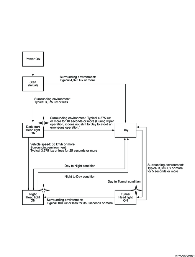
Conditions for the transition from day to night

Conditions for the transition from day to tunnel

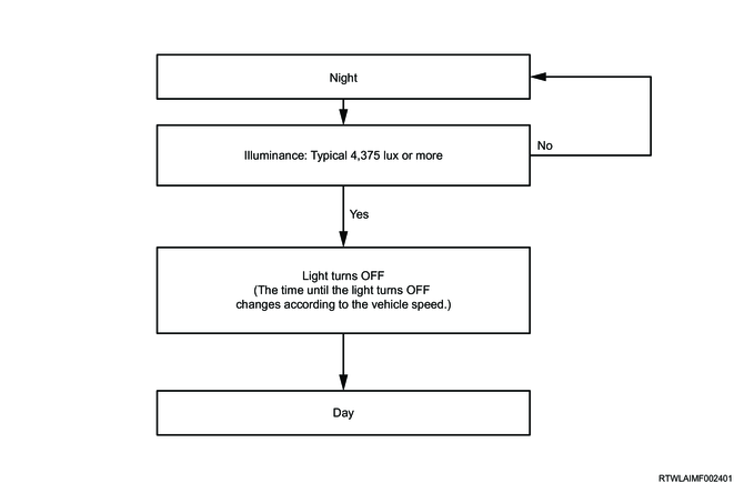
Conditions for the transition from night to day
3. Exterior light
The BCM controls the following lights according to the light control switch operation or various requests.
Front
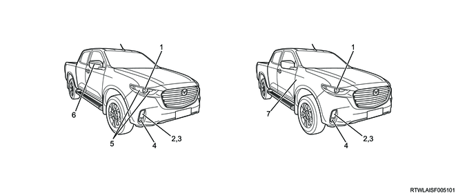
Legend
- Headlight
- Turn signal light
- Clearance light/daytime running light (except models for headlight with DRL)
- Front fog light
- Daytime running light (models for headlight with DRL)
- Turn signal light (outside rearview mirror mounted type)
- Turn signal light (front fender mounted type)
Rear (Except horizontal type)
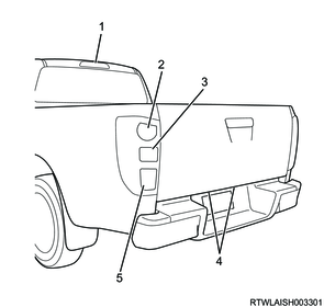
Legend
- High mounted stop light
- Taillight and stop light
- Turn signal light
- License plate light
- Backup light/rear fog light
Rear (Horizontal type)
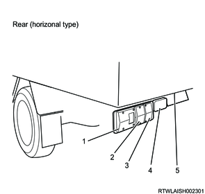
Legend
- Taillight and stop light
- Turn signal light
- Backup light
- Rear fog light
- License plate light
1) Clearance light/tail light/license plate light
When the light control switch is in the TAIL position, the BCM illuminates the clearance light, tail light, and license plate light. Also, with the AUTO position, the BCM illuminates the clearance light, tail light, and license plate light based on the illuminance signal received from the RLS.
2) Daytime running light (DRL)
The BCM turns ON or OFF the daytime running light (DRL) according to the vehicle conditions.
3) Head light (low beam)
When the light control switch is in the LO position, the BCM illuminates the headlight (low beam). Also, when the BCM receives the headlight request from the RLS while it is in the AUTO position, it illuminates the head light (low beam).
4) Head light (high beam)
When the light control switch is in the LO position and the high beam switch is ON, the BCM illuminates the head light (high beam).
5) Turn signal light
When the turn signal switch signal or hazard warning flasher switch signal is input, the BCM controls the turn signal light circuit and flashes the turn signal light. Also, it is flashed as a response action to the ESS, answer-back, and Impact Sensing Door Unlock function.
6) Stop light/high mounted stop light
When the stop light switch signal is input, the BCM controls the stop light circuit and illuminates the stop light. Also, at the time of the stop light output, the high mounted stop light illuminates simultaneously.
7) Backup light
When the reverse signal is input, the BCM controls the backup light circuit and illuminates the backup light.
8) Rear fog light
When the rear fog light ON signal is input to the BCM by the driver's rear fog light switch operation while the headlights are illuminated, the BCM turns ON the rear fog light relay output and illuminates the rear fog light.
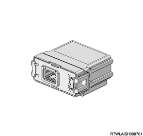
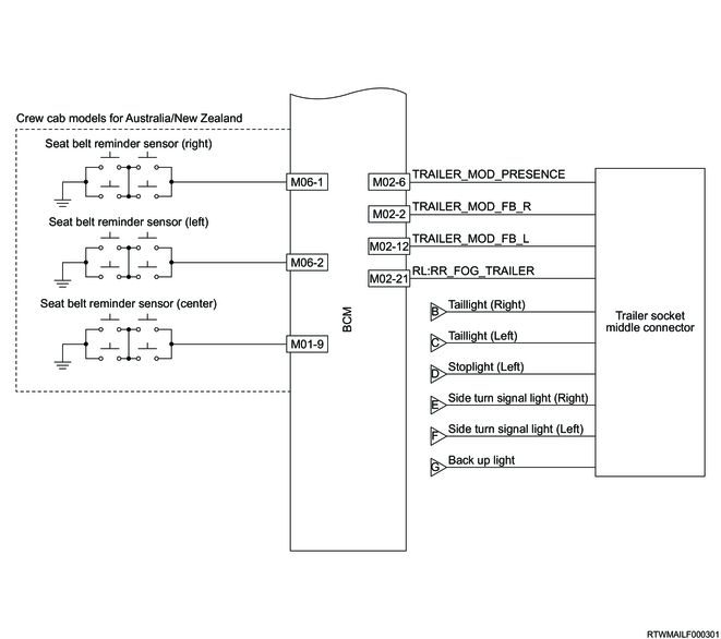
4. Trailer socket middle connector
The BCM outputs the illumination signal of each rear light to the trailer side via the trailer socket middle connector. Also, the BCM determines whether the trailer is connected or not based on the trailer detection signal input from the trailer side via the trailer socket middle connector.
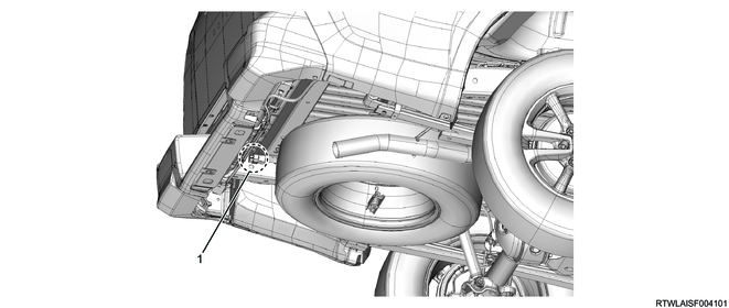
Legend
- Trailer socket middle connector
5. Interior lamp
The BCM controls the following lights according to the door switch or various requests.
Interior light components

Legend
- Dome light
- Map light
- Map light
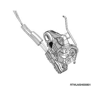
6. Door lock
The door unlock position switch and door lock motor are built into the door lock. The BCM detects the door unlock position switch signal. When the door lock/unlock switch signal or the door lock/unlock request from the wireless access module is input, the BCM controls the door lock motor circuit and activates the door lock motor.
7. Wiper motor
The wiper motor equipped to the vehicle differs depending on the wiper blade type, and the wiper controls by the BCM are different between each wiper motor.
Design blade & wiper motor
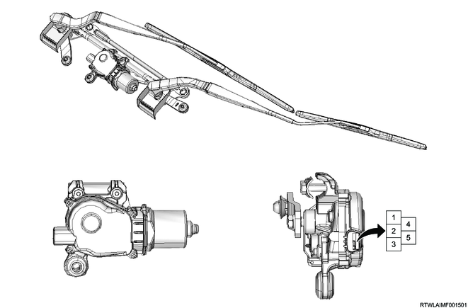
Note
- The illustration shows an RHD model.
| Pin No. |
Pin Function |
| 1 |
Power supply |
| 2 |
Ground |
| 3 |
Wiper Low |
| 4 |
CAM switch signal |
| 5 |
Wiper High |
For the wiper motor of design blade equipped models, the BCM controls the wiper relay and wiper H/L relay to enable the wiper operations according to the windshield wiper switch and adjustment ring positions. Also, the BCM monitors the wiper motor operation based on the CAM switch signal. When it is detected that the CAM switch signal does not match the wiper motor operation for approximately 5 seconds while the vehicle speed is 10 km/h or less, the BCM stops the wiper motor to protect the motor until the driver operates the windshield wiper switch again.
Flat blade & wiper motor

Note
- The illustration shows an RHD model.
| Pin No. |
Pin Function |
| 1 |
Power supply |
| 2 |
Ground |
| 3 |
Redundant |
| 4 |
LIN communication |
The wiper motor of the flat blade equipped models communicates with the BCM via the LIN communication circuit. The BCM sends the wiper speed request according to the windshield wiper switch and adjustment ring positions and the wiper speed request received from the RLS to the wiper motor in order to enable the wiper operations according to the requests.
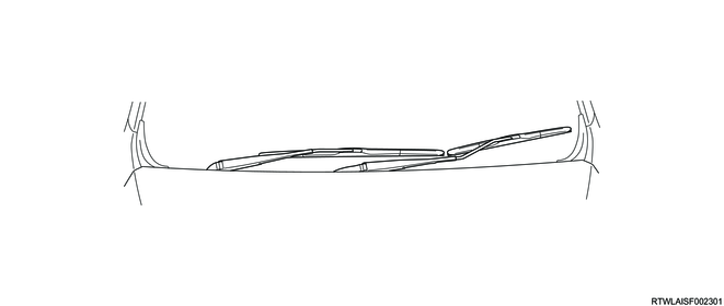
Also, for the wiper arm replacement of the flat blade equipped models, although the hood prevents the arm from rising, a specific operation can move the wiper arm to the service position. When the BCM receives the service position request, it sends the request for moving the arm to the service position to the wiper motor via the LIN communication.
The wiper motor of the flat blade equipped models has a self-diagnosis function, and if it detects a malfunction, the error information is sent to the BCM via the LIN communication.
8. Combination switch
The combination switch consists of the lighting switch, fog light switch, turn signal switch, wiper switch, and window washer switch. The BCM controls the exterior light, wiper, windshield washer, and turn signal light based on each switch signal.
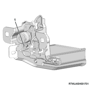
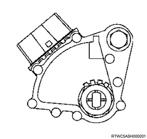
9. Key reminder switch
The key reminder switch is installed to the steering lock section. The key reminder switch detects that the key is inserted.
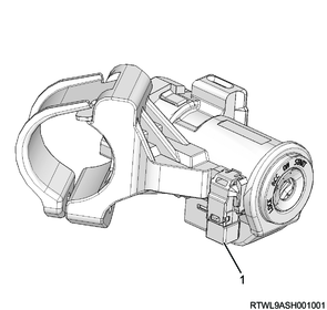
Legend
- Key reminder switch
10. Hazard warning flasher switch
The hazard warning flasher switch is a push lock type switch. When the hazard warning flasher switch is turned ON, the switch contact point is closed and the ground circuit is established. The BCM determines the switch ON/OFF status according to the voltage changes in the hazard warning flasher switch signal circuit.
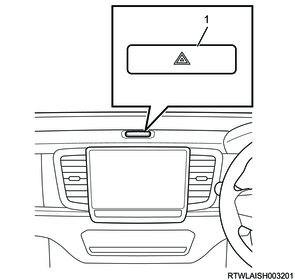
Legend
- Hazard warning flasher switch
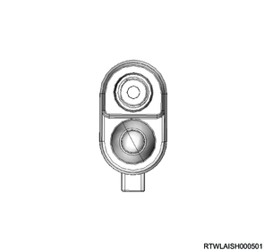
11. Stop light switch
The stop light switch is installed to the brake pedal bracket, and it detects the status of the driver's operation on the brake pedal. The stop light switch is a non-contact switch, and its ON/OFF output is controlled by the sensor in the switch. The BCM determines the switch ON/OFF status according to the voltage changes in the stoplight switch signal circuit.
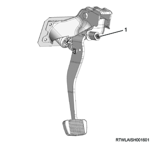
Legend
- Stop light switch
12. Door switch
The door switch detects the door open/closed state. The door switch is a normally closed switch that turns OFF when the door is closed and the switch contact point opens. The BCM determines the switch ON/OFF status according to the voltage changes in the door switch signal circuit.
13. Engine hood switch
The engine hood switch detects the opening or closing of the engine hood. The BCM determines the switch ON/OFF status according to the voltage changes in the engine hood switch signal circuit.
Legend
- Engine hood switch
14. Rear window defogger switch
The rear window defogger switch is installed to the control panel and control lever. When the BCM detects the rear window defogger switch signal, it controls the rear defogger relay.
Models with Automatic Air Conditioner

Legend
- Rear window defogger switch
Models with cooler/heater/manual air conditioner
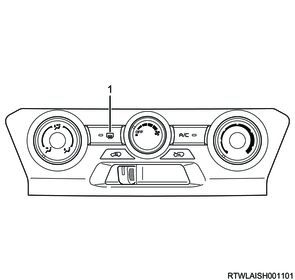
Legend
- Rear window defogger switch
15. Inhibitor switch (AT only)
The inhibitor switches are installed to the right side of the transmission, and detect the P, R, and N position signals of the selector lever. The BCM performs each control based on the input signal.
16. Backup light switch (MT only)
The backup light switch is installed to the transmission and it detects that the gear is in the reverse position. When the BCM detects that the gear position is reverse, the backup light illuminates.
17. Neutral switch (MT only)
The neutral switch is installed to the control box. It detects that the gear is in the neutral position.
18. Cruise control switch (Models with stereo cameras)
The operation signal from the cruise control switch is input to the BCM. BCM sends the following input switch operation signal to the stereo camera via the CAN communication circuit.
Cruise control switch
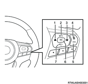
Legend
- Inter-vehicular distance switch
- SET/+ switch
- LKAS switch
- Main switch
- CANCEL switch
- RES switch
- SET/- switch
19. Blind spot indicator
The BCM controls the blind spot indicator illumination and flashing. The BCM receives the control information from the right and left radar sensor units via the CAN communication circuit. Also, when the illumination conditions for the clearance light are met, the BCM reduces the brightness of the blind spot indicator.
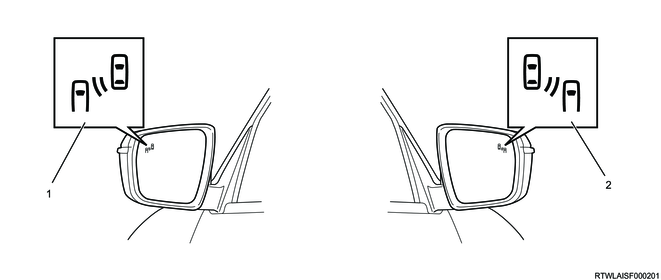
Legend
- Blind spot indicator (Left side)
- Blind spot indicator (Right side)
20. Seat belt reminder sensor (Crew cab models for Australia/New Zealand)
The signals from the seat belt reminder sensor built into the rear seat are input to the BCM. The BCM sends the input seat belt reminder sensor signal to the instrument panel cluster via the CAN communication circuit.
21. Instrument panel cluster
The BCM sends and receives the control information from and to the instrument panel cluster via the CAN communication circuit. The BCM sends the requests for sounding at the turn signal switch operation, indicating various indicators, illuminating warning lights, displaying on the MID, etc., to the instrument panel cluster via the CAN communication circuit. Also, the BCM receives the signals on the front fog light operating status from the instrument panel cluster.
Indicator light
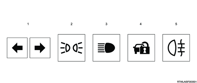
Legend
- Turn signal indicator light
- Light position indicator light
- High beam indicator light
- Anti-theft system indicator light
- Rear fog light indicator light
Warning light

Legend
- LED Headlight Warning Light (LED headlight model only)
Multi-information display

Legend
- LH Headlight failure
- RH Headlight failure
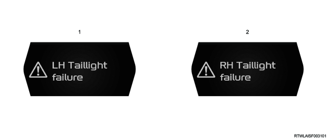
Legend
- LH Taillight failure
- RH Taillight failure

Legend
- Rear fog light failure
22. ECM
The BCM sends and receives the control information to and from the ECM via the CAN communication circuit. The BCM receives signals such as a vehicle speed signal and accelerator pedal position signal from the ECM.
4JJ3 engine models
RZ4E-TC engine models
23. TCM
The BCM sends and receives the control information to and from the TCM via the CAN communication circuit. The BCM receives a selector lever signal from the TCM.
24. EHCU
The BCM sends and receives the control information to and from the EHCU via the CAN communication circuit. The BCM receives the emergency stop signal (ESS) and stop light illumination request from the EHCU.
25. Wireless access module
The BCM receives the door lock/unlock request signal, answer-back request, welcome light request, etc., from the wireless access module via the CAN communication circuit.
Models with passive entry and start system
Except models with passive entry and start system
26. Stereo camera
The BCM sends and receives the control information to and from the stereo camera via the CAN communication circuit. The BCM sends the control information for steering switch signal, exterior light, wiper, etc. Also, the stereo camera sends an auto high beam request to the BCM.
13. General circuit diagram
BCM schematic circuit diagram 1/4
BCM schematic circuit diagram 2/4
BCM schematic circuit diagram 3/4
BCM schematic circuit diagram 4/4
BCM outline view and connector pin layout diagram
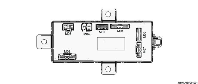
M01 (B16)
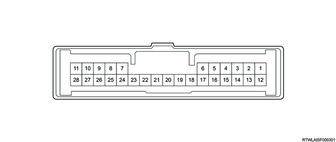
| M01 (28 pin connector) |
BCM |
||
| Pin No. |
Pin function |
High |
Low |
| 1 |
Front windshield washer switch signal |
O |
O |
| 2 |
Cruise control switch signal (RES switch, Inter-vehicular distance switch, LKAS switch) |
O |
- |
| 3 |
- |
- |
- |
| 4 |
- |
- |
- |
| 5 |
- |
- |
- |
| 6 |
- |
- |
- |
| 7 |
- |
- |
- |
| 8 |
- |
- |
- |
| 9 |
Rear seat belt reminder sensor signal (center) |
O |
- |
| 10 |
Light control switch (Taillight) signal |
O |
O |
| 11 |
Light control switch (Headlight) signal |
O |
O |
| 12 |
Light control switch (AUTO) signal |
O |
- |
| 13 |
Light control switch (Passing) signal |
O |
O |
| 14 |
Light control switch (High beam) signal |
O |
O |
| 15 |
Rear fog light switch signal |
O |
O |
| 16 |
- |
- |
- |
| 17 |
- |
- |
- |
| 18 |
- |
- |
- |
| 19 |
Cruise control switch ground |
O |
- |
| 20 |
Cruise control switch signal (Main switch, CANCEL switch, SET/+ switch, SET/- switch) |
O |
- |
| 21 |
Adjustment ring ground |
O |
O |
| 22 |
Adjustment ring (+) |
O |
O |
| 23 |
Ground |
O |
O |
| 24 |
Front windshield wiper switch (AUTO/INT) signal |
O |
O |
| 25 |
Front windshield wiper switch (HI) signal |
O |
O |
| 26 |
Front windshield wiper switch (LO) signal |
O |
O |
| 27 |
Turn signal switch (Left) signal |
O |
O |
| 28 |
Turn signal switch (Right) signal |
O |
O |
M02 (C17)
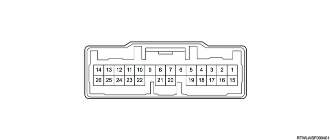
| M02 (26 pin connector) |
BCM |
||
| Pin No. |
Pin function |
High |
Low |
| 1 |
- |
- |
- |
| 2 |
- |
- |
- |
| 3 |
Reverse switch signal (AT) Backup light switch signal (MT) |
O |
O |
| 4 |
Neutral switch signal |
O |
O |
| 5 |
Parking switch signal |
O |
O |
| 6 |
Trailer detection signal (For Australia/New Zealand) |
O |
- |
| 7 |
Turn signal light (Front right) control |
O |
O |
| 8 |
Turn signal light (Rear left) control |
O |
O |
| 9 |
Turn signal light (Rear right) control |
O |
O |
| 10 |
Turn signal light (Front left) control |
O |
O |
| 11 |
Engine hood switch signal |
O |
O |
| 12 |
- |
- |
- |
| 13 |
- |
- |
- |
| 14 |
Anti theft horn control |
O |
- |
| 15 |
- |
- |
- |
| 16 |
- |
- |
- |
| 17 |
- |
- |
- |
| 18 |
- |
- |
- |
| 19 |
- |
- |
- |
| 20 |
Stop light switch signal |
O |
O |
| 21 |
- |
- |
- |
| 22 |
- |
- |
- |
| 23 |
Rear fog light control |
O |
O |
| 24 |
Front wiper cam switch signal (With conventional wiper motor) |
O |
O |
| 25 |
Front windshield wiper redundant output (Variable intermittent windshield wiper control) [Without conventional wiper motor] |
O |
- |
| Front wiper relay control (With conventional wiper motor) |
O |
O |
|
| 26 |
- |
- |
- |
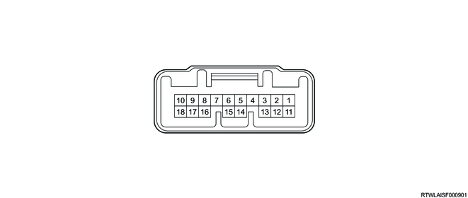
M03 (C18)

| M03 (18 pin connector) |
BCM |
||
| Pin No. |
Pin function |
High |
Low |
| 1 |
Taillight (Right) control |
O |
O |
| 2 |
Taillight (Left) control |
O |
O |
| 3 |
Stop light (Left) control |
O |
O |
| 4 |
- |
- |
- |
| 5 |
Backup light control |
O |
O |
| 6 |
Headlight (Left side high beam) control |
O |
O |
| 7 |
Headlight (Right side low beam) control |
O |
O |
| 8 |
Daytime running light (left) relay control |
O |
- |
| 9 |
Clearance light (Right) control |
O |
O |
| 10 |
- |
- |
- |
| 11 |
Clearance light (Left) control |
O |
O |
| 12 |
Headlight (Left side low beam) control |
O |
O |
| 13 |
Headlight (Right side high beam) control |
O |
O |
| 14 |
Daytime running light (right) relay control |
O |
O |
| 15 |
LED headlight (Right) feedback signal |
O |
- |
| 16 |
LED headlight (Left) feedback signal |
O |
- |
| 17 |
- |
- |
- |
| 18 |
Stop light (Right) control |
O |
O |
M04 (B17)
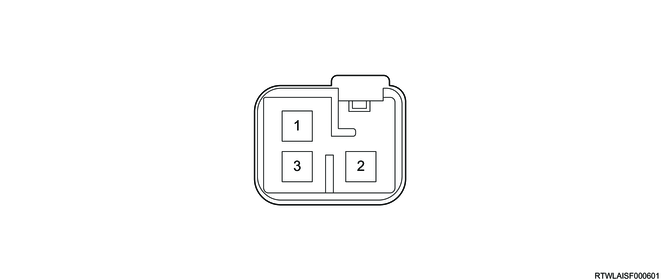
| M04 (3 pin connector) |
BCM |
||
| Pin No. |
Pin function |
High |
Low |
| 1 |
Battery voltage |
O |
O |
| 2 |
Battery voltage |
O |
O |
| 3 |
Battery voltage |
O |
O |
M05 (B18)
| M05 (20 pin connector) |
BCM |
||
| Pin No. |
Pin function |
High |
Low |
| 1 |
- |
- |
- |
| 2 |
- |
- |
- |
| 3 |
CAN low signal |
O |
O |
| 4 |
CAN high signal |
O |
O |
| 5 |
Side turn signal light (Right) control |
O |
O |
| 6 |
Side turn signal light (Left) control |
O |
O |
| 7 |
- |
- |
- |
| 8 |
Blind spot indicator (Left) control |
O |
- |
| 9 |
Blind spot indicator (Right) control |
O |
- |
| 10 |
- |
- |
- |
| 11 |
LIN signal |
O |
- |
| 12 |
Illumination light control |
O |
O |
| 13 |
Front windshield washer relay control (Without conventional wiper motor) |
O |
- |
| Front wiper HI/LO relay control (With conventional wiper motor) |
O |
O |
|
| 14 |
- |
- |
- |
| 15 |
- |
- |
- |
| 16 |
Rear defogger relay control |
O |
O |
| 17 |
- |
- |
- |
| 18 |
- |
- |
- |
| 19 |
- |
- |
- |
| 20 |
- |
- |
- |
M06 (B19)

| M06 (22 pin connector) |
BCM |
||
| Pin No. |
Pin function |
High |
Low |
| 1 |
Rear seat belt reminder sensor signal (right) |
O |
- |
| 2 |
Rear seat belt reminder sensor signal (left) |
O |
- |
| 3 |
Accessory voltage |
O |
O |
| 4 |
Rain light sensor (RLS) power supply |
O |
- |
| 5 |
Door switch (Front right) signal |
O |
O |
| 6 |
Door switch (Rear left) signal |
O |
O |
| 7 |
Door switch (Front left) signal |
O |
O |
| 8 |
Door unlock position switch (Rear right & left) signal |
O |
- |
| 9 |
Door unlock position (Front left) switch signal |
O |
- |
| 10 |
Door unlock position (Front right) switch signal |
O |
- |
| 11 |
Door unlock switch signal (Key switch) |
O |
O |
| 12 |
Door lock switch signal (Key switch) |
O |
O |
| 13 |
Ignition voltage |
O |
O |
| 14 |
Door switch (Rear right) signal |
O |
O |
| 15 |
Airbag deployment signal |
O |
O |
| 16 |
- |
- |
- |
| 17 |
- |
- |
- |
| 18 |
Power door unlock switch signal |
O |
O |
| 19 |
Power door lock switch signal |
O |
O |
| 20 |
Key reminder switch signal |
O |
O |
| 21 |
Rear window defogger switch signal |
O |
O |
| 22 |
Hazard warning flasher switch signal |
O |
O |
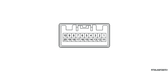
M07 (B20)
| M07 (18 pin connector) |
BCM |
||
| Pin No. |
Pin function |
High |
Low |
| 1 |
Interior light control high side |
O |
O |
| 2 |
Door lock control (Passenger side) |
O |
- |
| 3 |
- |
- |
- |
| 4 |
Anti-theft system indicator light control |
O |
- |
| 5 |
- |
- |
- |
| 6 |
- |
- |
- |
| 7 |
- |
- |
- |
| 8 |
- |
- |
- |
| 9 |
Ground |
O |
O |
| 10 |
Ground |
O |
O |
| 11 |
Battery voltage (door lock/unlock) |
O |
O |
| 12 |
Door lock control (Rear) |
O |
- |
| 13 |
- |
- |
- |
| 14 |
- |
- |
- |
| 15 |
- |
- |
- |
| 16 |
Interior light control low side |
O |
O |
| 17 |
Door unlock control/Door unlock control (Driver side) |
O |
O |
| 18 |
Door lock control |
O |
O |