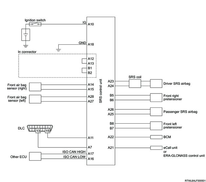
1. SRS control unit schematic circuit diagram (Except models with side airbags and curtain airbags)
2. SRS control unit outline view and connector pin layout (Except models with side airbags and curtain airbags)
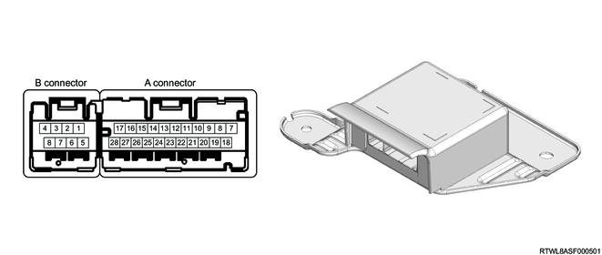
| PIN No. |
Pin function |
| 1 |
- |
| 2 |
- |
| 3 |
- |
| 4 |
- |
| 5 |
- |
| 6 |
- |
| 7 |
Diagnostic request signal input |
| 8 |
- |
| 9 |
- |
| 10 |
Ignition voltage input |
| 11 |
Batch deployment processing terminal (ACL) |
| 12 |
Connector mating check terminal |
| 13 |
Connector mating check terminal |
| 14 |
Front airbag sensor right (+) input |
| 15 |
Front airbag sensor right (-) input |
| 16 |
ISO CAN (Low) |
| 17 |
ISO CAN (High) |
| 18 |
Ground |
| 19 |
- |
| 20 |
- |
| 21 |
Deployment output to eCall unit/FRA-GLONASS control unit |
| 22 |
Deployment output to BCM |
| 23 |
Driver airbag deployment current output (High) |
| 24 |
Driver airbag deployment current output (Low) |
| 25 |
Passenger airbag deployment current output (Low) |
| 26 |
Passenger airbag deployment current output (High) |
| 27 |
Front airbag sensor left (-) input |
| 28 |
Front airbag sensor left (+) input |
| PIN No. |
Pin function |
| 1 |
Connector mating check terminal |
| 2 |
Connector mating check terminal |
| 3 |
- |
| 4 |
- |
| 5 |
Front right side pretensioner ignition current output (High) |
| 6 |
Front right side pretensioner ignition current output (Low) |
| 7 |
Front left side pretensioner ignition current output (Low) |
| 8 |
Front left side pretensioner ignition current output (High) |