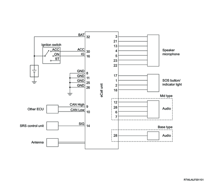
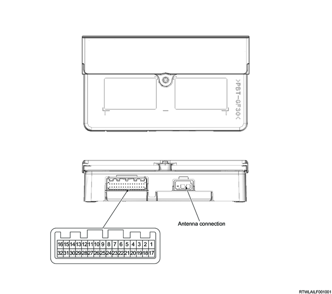
Pin No.
|
Pin function
|
1
|
Indicator light (red) control
|
2
|
Indicator light (green) control
|
3
|
Speaker microphone power supply
|
4
|
Speaker microphone input (+)
|
5
|
Speaker microphone input (-)
|
6
|
Speaker microphone output (+)
|
7
|
Speaker microphone output (-)
|
8
|
Ground
|
9
|
CAN (High)
|
10
|
CAN (Low)
|
11
|
Ground
|
12
|
UART communication
|
13
|
UART communication
|
14
|
Air bag active PWM signal
|
15
|
-
|
16
|
Ignition power supply
|
17
|
SOS button signal
|
18
|
SOS button / Indicator light ground
|
19
|
-
|
20
|
-
|
21
|
Speaker microphone ground
|
22
|
Speaker output (-)
|
23
|
Speaker output (+)
|
24
|
-
|
25
|
Ground
|
26
|
Ground
|
27
|
-
|
28
|
Mute control
|
29
|
-
|
30
|
Accessory power supply
|
31
|
-
|
32
|
Battery power supply
|