 |
am6zzw00014443
DTC P0401:00 [PCM (SKYACTIV-D 2.2)]
id0102j5704200
Engine Type
|
Item |
Reference |
|---|---|
|
Fuel injector (6 pin type), Without SCR System
|
|
|
Fuel injector (6 pin type), With SCR System
|
Fuel injector (6 pin type), Without SCR System
Details On DTCs
|
DESCRIPTION |
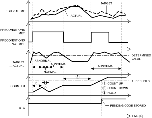
EGR flow insufficient detected |
|
|---|---|---|
|
DETECTION CONDITION
|
Determination conditions
|
• The EGR volume is lower than the specification for the target value for a continuous specified time.
|
|
Preconditions
|
• During EGR control
• Engine speed: 1,300—2,500 rpm
• Fuel injection amount:15—50 mm3/stoke
• Engine torque: 80—240 N·m {8.2—24 kgf·m, 60—177 ft·lbf}
|
|
|
Drive cycle
|
• 2
|
|
|
Self test type
|
• CMDTC self test
|
|
|
Sensor used
|
• EGR valve
• Intake shutter valve
• MAF sensor
• MAP sensor No.2
• Boost air temperature sensor
• Exhaust gas pressure sensor No.1
• Exhaust gas temperature sensor No.1
|
|
|
FAIL-SAFE FUNCTION
|
• Inhibits engine-stop by operating the i-stop function.
|
|
|
VEHICLE STATUS WHEN DTCs ARE OUTPUT
|
• Check engine light is illuminated
|
|
|
POSSIBLE CAUSE
|
• Erratic signal to PCM
• Intake shutter valve malfunction
• EGR valve malfunction (stuck close)
• Air suction in intake air system between turbocharger and intake manifold
• EGR system passage malfunction (restriction)
• PCM malfunction
|
|
System Wiring Diagram
Function Explanation (DTC Detection Outline)
am6zzw00014443
|
Repeatability Verification Procedure
PID Item/Simulation Item Used In Diagnosis
|
Item |
Definition |
Unit |
Condition/Specification |
|---|---|---|---|
|
EXHPRES1
|
Exhaust gas pressure (No.1)
|
KPa {MPa}, mBar {Bar}, psi, in H20
|
• Idle (after warm up): Approx. 100 kPa {1 bar, 14.5 psi}
• Racing (engine speed above 2,000 rpm): Approx. 125 kPa {1.27 kgf/cm2, 18.1 psi}
• Racing (engine speed above 4,000 rpm): Approx. 245 kPa {2.50 kgf/cm2, 35.5 psi}
|
|
EXHTEMP1
|
Exhaust gas temperature (No.1)
|
°C, °F
|
Displays the exhaust gas temperature
|
|
CACT12
|
Boost air temperature
|
°C, °F
|
Displays the boost air temperature
|
|
MAF
|
Mass air flow
|
g/sec
|
• Switch ignition ON (engine off): Approx. 0.4 g/sec {0.13 Ib/min}
• Idle (after warm up): Approx. 3.2 g/sec {0.42 Ib/min}
• Racing (engine speed above 2,000 rpm): Approx. 9.2 g/sec {1.12 Ib/min}
• Racing (engine speed above 4,000 rpm): Approx. 70 g/sec {9.3 Ib/min}
|
|
MAP
|
Manifold absolute pressure
|
KPa {MPa}, mBar {Bar}, psi, in H20
|
• Switch ignition ON (engine off): Approx. 100 kPa {1 bar, 14.5 psi}
• Idle: Approx. 80 kPa {0.8 bar, 12 psi}
|
Function Inspection Using M-MDS
|
STEP |
INSPECTION |
ACTION |
|
|---|---|---|---|
|
1
|
PURPOSE: VERIFY RELATED SERVICE INFORMATION AVAILABILITY
• Verify related Service Information availability.
• Is any related Service Information available?
|
Yes
|
Perform repair or diagnosis according to the available Service Information.
• If the vehicle is not repaired, go to the next step.
|
|
No
|
Go to the next step.
|
||
|
2
|
PURPOSE: IDENTIFY TRIGGER DTC FOR FREEZE FRAME DATA
• Is the DTC P0401:00 on FREEZE FRAME DATA?
|
Yes
|
Go to the next step.
|
|
No
|
Go to the troubleshooting procedure for DTC on FREEZE FRAME DATA.
|
||
|
3
|
PURPOSE: RECORD VEHICLE STATUS AT TIME OF DTC DETECTION TO UTILIZE WITH REPEATABILITY VERIFICATION
• Record the FREEZE FRAME DATA/snapshot data on the repair order.
|
—
|
Go to the next step.
|
|
4
|
PURPOSE: VERIFY IF DIAGNOSTIC RESULT IS AFFECTED BY OTHER RELATED DTCs OCCURRING
• Switch the ignition off, then ON (engine off).
• Perform the Pending Trouble Code Access Procedure and DTC Reading Procedure.
• Is the other PENDING CODE/DTC also present?
|
Yes
|
Go to the applicable DTC inspection.
|
|
No
|
Go to the next step.
|
||
|
5
|
PURPOSE: VERIFY IF THERE IS PID ITEM CAUSING DRASTIC CHANGES OF ACCELERATION FLUCTUATION BY INPUT SIGNAL TO PCM
• Access the following PIDs using the M-MDS:
• Is there any signal that is far out of specification?
|
Yes
|
Go to the next step.
|
|
No
|
Go to the troubleshooting procedure to perform the procedure from Step 1.
|
||
|
6
|
PURPOSE: VERIFY CONNECTOR CONNECTIONS
• Access the following PIDs using the M-MDS:
• When the following parts are shaken, does the PID value include a PID item which has changed?
|
Yes
|
Inspect the related wiring harness and connector.
• Repair or replace the malfunctioning part.
Go to the troubleshooting procedure to perform the procedure from Step 5.
|
|
No
|
Go to the troubleshooting procedure to perform the procedure from Step 1.
|
||
Troubleshooting Diagnostic Procedure
|
STEP |
INSPECTION |
ACTION |
|
|---|---|---|---|
|
1
|
PURPOSE: INSPECT INTAKE SHUTTER VALVE CONTROL SYSTEM OPERATION
• Perform the Intake Shutter Valve Operation Inspection.
• Is there any malfunction?
|
Yes
|
Repair or replace the malfunctioning part according to the inspection results, then go to Step 5.
|
|
No
|
Go to the next step.
|
||
|
2
|
PURPOSE: INSPECT EGR VALVE CONTROL SYSTEM OPERATION
• Perform the EGR Valve Operation Inspection.
• Is there any malfunction?
|
Yes
|
Repair or replace the malfunctioning part according to the inspection results, then go to Step 5.
|
|
No
|
Go to the next step.
|
||
|
3
|
PURPOSE: INSPECT INTAKE AIR SYSTEM FOR AIR SUCTION
• Inspect for air leakage at the following:
• Is there any malfunction?
|
Yes
|
Repair or replace the malfunctioning part according to the inspection results, then go to Step 5.
|
|
No
|
Go to the next step.
|
||
|
4
|
PURPOSE: INSPECT FOR RESTRICTION OR CLOGGED IN EGR PASSAGE
• Switch the ignition off.
• Remove the EGR valve.
• Visually inspect the EGR passage for clogging and the gasket correctly installed.
• Is there any malfunction?
|
Yes
|
Repair or replace the malfunctioning part according to the inspection results, then go to the next step.
(If there is clogging caused by soot in the EGR valve, inspect around the EGR piping and clean or replace it.)
|
|
No
|
Go to the next step.
|
||
|
5
|
PURPOSE: PERFORM DTC INSPECTION AND VERIFY IF MALFUNCTIONING PART IS PCM
• Always reconnect all disconnected connectors.
• Clear the DTC from the PCM memory using the M-MDS.
• Implement the repeatability verification procedure.
• Perform the Pending Trouble Code Access Procedure.
• Is the PENDING CODE for this DTC present?
|
Yes
|
Repeat the inspection from Step 1.
• If the malfunction recurs, replace the PCM.
Go to the next step.
|
|
No
|
Go to the next step.
|
||
|
6
|
PURPOSE: VERIFY AFTER REPAIR PROCEDURE
• Perform the “AFTER REPAIR PROCEDURE”.
• Are any DTCs present?
|
Yes
|
Go to the applicable DTC inspection.
|
|
No
|
DTC troubleshooting completed.
|
||
Fuel injector (6 pin type), With SCR System
Details on DTCs
|
System malfunction location |
EGR control system: Insufficient amount of EGR |
|
|---|---|---|
|
Detection condition
|
Determination conditions
|
• The EGR volume is less than 0.16 g/rev for the target value for a continuous 8.2 s.
|
|
Preconditions
|
• During EGR control
• Engine speed: 1,300―6,000 rpm
• Fuel injection amount: 15―50 mm3/st
• Engine torque: 80―240 N·m {8.2―24 kgf·m, 60―177 ft·lbf}
• The following DTCs are not detected
|
|
|
Drive cycle
|
• 2
|
|
|
Self-test type
|
• CMDTC self test
|
|
|
Sensor/unit used
|
• EGR valve
• EGR cooler bypass valve
• Intake shutter valve
• MAF sensor
• MAP sensor No.2
• Boost air temperature sensor
• Exhaust gas pressure sensor No.1
• Exhaust gas temperature sensor No.1
|
|
|
Fail-safe
|
• Not applicable
|
|
|
Vehicle status when DTCs are output
|
• Check engine light turns on
|
|
|
Possible Cause
|
• PCM input signal error
• Intake shutter valve malfunction
• EGR valve malfunction (stuck closed)
• EGR cooler bypass valve malfunction (stuck closed)
• Air suction from intake-air system piping (between turbocharger and intake manifold)
• EGR malfunction (clogging in EGR piping)
• PCM malfunction
|
|
System Wiring Diagram
Function Explanation (DTC Detection Outline)
am6zzw00014443
|
Repeatability Verification Procedure
PID Item/Simulation Item Used in Diagnosis
PID
|
Item name |
Outline |
Unit |
Display/condition |
|---|---|---|---|
|
EXHPRES1
|
Exhaust gas pressure (No.1)
|
kPa
|
• Idle: Approx. 100 kPa {1.02 kgf/cm2, 14.5 psi}
• Racing (engine speed 4,000 rpm): Approx. 193 kPa {1.97 kgf/cm2, 28.0 psi}
• Racing (engine speed 5,000 rpm): Approx. 266 kPa {2.71 kgf/cm2, 38.6 psi}
|
|
EXHTEMP1
|
Exhaust gas temperature (No.1)
|
°C
|
• Displays exhaust gas temperature (No.1)
|
|
CACT12
|
Boost air temperature
|
°C
|
• Displays boost air temperature
|
|
MAF
|
Intake air amount
|
g/sec
|
• Ignition switched ON: Approx. 1.0 g/sec
• Idle: Approx. 5.4 g/sec
• Racing (engine speed 2,000 rpm): Approx. 13.84 g/sec
• Racing (engine speed 4,000 rpm): Approx. 85.13 g/sec
|
|
MAP
|
Intake air pressure
|
kPa
|
• Displays intake air pressure (No.2)
|
Function Inspection Using M-MDS
|
Step |
Inspection |
Results |
Action |
|---|---|---|---|
|
1
|
PURPOSE: VERIFY DTC CAUSING FREEZE FRAME DATA
• Is DTC P0401:00 causing the freeze frame data?
|
Yes
|
Go to the next step.
|
|
No
|
Inspect the DTC causing the freeze frame data.
|
||
|
2
|
PURPOSE: RECORD VEHICLE STATUS AT TIME OF DTC DETECTION TO UTILIZE WITH REPEATABILITY VERIFICATION
• Record the freeze frame data/snap shot data.
|
―
|
Go to the next step.
|
|
3
|
PURPOSE: VERIFY OTHER RELATED DTCs
• Switch the ignition OFF, and then switch it ON (engine off).
• Display the DTCs using the M-MDS.
• Has any DTC other than P0401:00 been stored?
|
Yes
|
Repair the malfunctioning location according to the applicable DTC troubleshooting.
|
|
No
|
Go to the next step.
|
||
|
4
|
PURPOSE: VERIFY RELATED SENSOR INPUT SIGNAL
• Start the engine and warm it up.
• Display the following PIDs using the M-MDS.
• Are the monitoring values normal?
|
Yes
|
Go to Troubleshooting Diagnostic Procedure to perform the procedure from step 1.
|
|
No
|
Go to the next step.
|
||
|
5
|
PURPOSE: INSPECT WIRING HARNESSES AND CONNECTORS FOR RELATED-SENSOR
• Display the following PIDs using the M-MDS.
• When the PCM, MAF sensor, MAP sensor No.2, boost air temperature sensor, exhaust gas pressure sensor No.1, and exhaust gas temperature sensor No.1 connectors are shaken, does the PID value include a PID item which has changed?
|
Yes
|
Inspect the related wiring harnesses and connectors.
• Repair or replace the malfunctioning location.
Go to Troubleshooting Diagnostic Procedure to perform the procedure from step 6.
|
|
No
|
Go to Troubleshooting Diagnostic Procedure to perform the procedure from step 1.
|
Troubleshooting Diagnostic Procedure
|
Step |
Inspection |
Results |
Action |
|---|---|---|---|
|
1
|
PURPOSE: INSPECT INTAKE SHUTTER VALVE
• Inspect the intake shutter valve.
• Is the intake shutter valve normal?
|
Yes
|
Go to the next step.
|
|
No
|
Replace the intake shutter valve, then go to the Step 6.
|
||
|
2
|
PURPOSE: VERIFY EGR VALVE OPERATION CONDITION
• Perform the EGR control inspection.
• Is the EGR valve operation normal?
|
Yes
|
Go to the next step.
|
|
No
|
Repair or replace the malfunctioning location, then go to Step 6.
|
||
|
3
|
PURPOSE: VERIFY EGR COOLER BYPASS VALVE OPERATION CONDITION
• Perform the EGR control inspection.
• Is the EGR cooler bypass valve operation normal?
|
Yes
|
Go to the next step.
|
|
No
|
Repair or replace the malfunctioning location, then go to Step 6.
|
||
|
4
|
PURPOSE: INSPECT INTAKE AIR SYSTEM FOR AIR SUCTION
• Visually inspect the following parts of the intake air system for looseness or damage.
• Is the intake air system normal?
|
Yes
|
Go to the next step.
|
|
No
|
Repair or replace the malfunctioning location, then go to Step 6.
|
||
|
5
|
PURPOSE: INSPECT EGR PASSAGE FOR CLOGGING
• Switch the ignition OFF.
• Remove the EGR valve.
• Is the gasket correctly installed? Visually inspect the EGR passage for clogging.
• Is the EGR passage normal?
|
Yes
|
Go to the next step.
|
|
No
|
Repair or replace the malfunctioning location, then go to the next step.
(If there is clogging caused by soot in the EGR valve, inspect around the EGR piping and clean or replace it)
|
||
|
6
|
PURPOSE: VERIFICATION OF VEHICLE REPAIR COMPLETION
• Reconnect all disconnected connectors and hoses.
• Refer to the [MEMORY CLEARING PROCEDURE] and clear the DTC.
• Implement the repeatability verification procedure.
• Display the DTCs using the M-MDS.
• Is DTC P0401:00 displayed?
|
Yes
|
Repeat the inspection from Step 1.
• If the malfunction recurs, replace the PCM, then go to the next step.
|
|
No
|
Go to the next step.
|
||
|
7
|
PURPOSE: VERIFY IF THERE IS ANY OTHER MALFUNCTION
• Has any other DTC or pending code been stored?
|
Yes
|
Repair the malfunctioning location according to the applicable DTC troubleshooting.
|
|
No
|
DTC troubleshooting completed.
|