|
1
|
RECORD VEHICLE STATUS AT TIME OF DTC DETECTION TO UTILIZE WITH REPEATABILITY VERIFICATION
-
Note
-
• Recording can be facilitated using the screen capture function of the PC.
• Record the snapshot data on the repair order.
|
—
|
Go to the next step.
|
|
2
|
VERIFY RELATED REPAIR INFORMATION AVAILABILITY
• Verify related Service Information availability.
• Is any related Service Information available?
|
Yes
|
Perform repair or diagnosis according to the available Service Information.
• If the vehicle is not repaired, go to the next step.
|
|
No
|
Go to the next step.
|
|
3
|
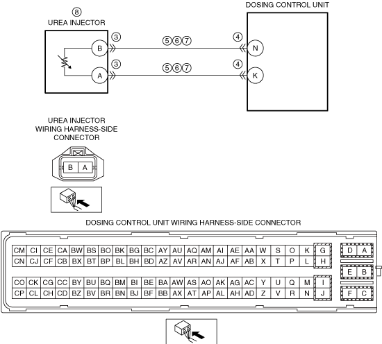
INSPECT UREA INJECTOR CONNECTOR CONDITION
• Switch the ignition off.
• Disconnect the urea injector connector.
• Inspect for poor connection (such as damaged/pulled-out pins, corrosion).
• Is there any malfunction?
|
Yes
|
Repair or replace the connector and/or terminals, then go to Step 9.
|
|
No
|
Go to the next step.
|
|
4
|
INSPECT DOSING CONTROL UNIT CONNECTOR CONDITION
• Disconnect the dosing control unit connector.
• Inspect for poor connection (such as damaged/pulled-out pins, corrosion).
• Is there any malfunction?
|
Yes
|
Repair or replace the connector and/or terminals, then go to Step 9.
|
|
No
|
Go to the next step.
|
|
5
|
INSPECT UREA INJECTOR CIRCUIT FOR SHORT TO GROUND
• Verify that the urea injector and dosing control unit connectors are disconnected.
• Inspect for continuity between the following terminals (wiring harness-side) and body ground:
-
― Urea injector terminal B
― Urea injector terminal A
• Is there continuity?
|
Yes
|
Refer to the wiring diagram and verify whether or not there is a common connector between the following terminals:
• Urea injector terminal B—dosing control unit terminal N
• Urea injector terminal A—dosing control unit terminal K
If there is a common connector:
• Determine the malfunctioning part by inspecting the common connector and the terminal for corrosion, damage, or pin disconnection, and the common wiring harness for a short to ground.
• Repair or replace the malfunctioning part.
If there is no common connector:
• Repair or replace the wiring harness which has a short to ground.
Go to Step 9.
|
|
No
|
Go to the next step.
|
|
6
|
INSPECT UREA INJECTOR CIRCUIT FOR SHORT TO POWER SUPPLY
• Verify that the urea injector and dosing control unit connectors are disconnected.
• Switch the ignition ON (engine off).
• Measure the voltage at the following terminals (wiring harness-side):
-
― Urea injector terminal B
― Urea injector terminal A
• Is the voltage 0 V?
|
Yes
|
Go to the next step.
|
|
No
|
Refer to the wiring diagram and verify whether or not there is a common connector between the following terminals:
• Urea injector terminal B—dosing control unit terminal N
• Urea injector terminal A—dosing control unit terminal K
If there is a common connector:
• Determine the malfunctioning part by inspecting the common connector and the terminal for corrosion, damage, or pin disconnection, and the common wiring harness for an open circuit.
If there is no common connector:
• Repair or replace the wiring harness which has an open circuit.
Go to Step 9.
|
|
7
|
INSPECT UREA INJECTOR CIRCUIT FOR OPEN CIRCUIT
• Verify that the urea injector and dosing control unit connectors are disconnected.
• Inspect for continuity between the following terminals (wiring harness-side):
-
― Urea injector terminal B—dosing control unit terminal N
― Urea injector terminal A—dosing control unit terminal K
• Is there continuity?
|
Yes
|
Go to the next step.
|
|
No
|
Refer to the wiring diagram and verify whether or not there is a common connector between the following terminals:
• Urea injector terminal B—dosing control unit terminal N
• Urea injector terminal A—dosing control unit terminal K
If there is a common connector:
• Determine the malfunctioning part by inspecting the common connector and the terminal for corrosion, damage, or pin disconnection, and the common wiring harness for an open circuit.
• Repair or replace the malfunctioning part.
If there is no common connector:
• Repair or replace the wiring harness which has an open circuit.
Go to Step 9.
|
|
8
|
INSPECT UREA INJECTOR
• Inspect the urea injector.
• Is there any malfunction?
|
Yes
|
Replace the urea injector, then go to the next step.
|
|
No
|
Go to the next step.
|
|
9
|
VERIFY THAT ENGINE CAN BE STARTED
• Always reconnect all disconnected connectors.
• Clear the DTC from the dosing control unit memory using the M-MDS.
-
Note
-
• The engine cannot be restarted when the remaining distance to empty is 0 km {0 mile}.
• Start the engine.
• Can the engine be started?
|
Yes
|
Go to the next step.
|
|
No
|
Perform the “SCR INDUCEMENT INSPECTION SERVICE FUNCTION” using the M-MDS.
-
Note
-
• When restriction of the remaining distance to empty is canceled, the SCR system warning light/SCR system warning indication turns off.
Go to the next step.
|
|
10
|
IMPLEMENT THE REPEATABILITY VERIFICATION PROCEDURE
• Always reconnect all disconnected connectors.
• Start the engine and leave it idling for 10 s.
• Has the restriction of the remaining distance to empty been canceled?
|
Yes
|
Go to the next step.
|
|
No
|
Repeat the inspection from Step 9.
|
|
11
|
VERIFY DTC TROUBLESHOOTING COMPLETED
• Retrieve the dosing control unit DTCs using the M-MDS.
• Is the same Pending DTC present?
|
Yes
|
Go to the next step.
|
|
No
|
Repeat the inspection from Step 1.
• If the malfunction recurs, replace the dosing control unit.
Go to the next step.
|
|
12
|
VERIFY IF OTHER DTCs DISPLAYED
• Are any other DTCs displayed?
|
Yes
|
Repair or replace the malfunctioning part according to the applicable DTC troubleshooting.
|
|
No
|
DTC troubleshooting completed.
|