|
1
|
VERIFY RELATED REPAIR INFORMATION AVAILABILITY
• Verify related Service Information availability.
• Is any related Service Information available?
|
Yes
|
Perform repair or diagnosis according to the available Service Information.
• If the vehicle is not repaired, go to the next step.
|
|
No
|
Go to the next step.
|
|
2
|
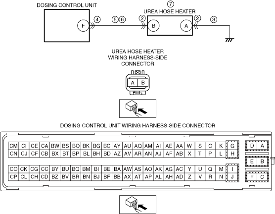
INSPECT UREA HOSE HEATER CONNECTOR CONDITION
• Switch the ignition off.
• Disconnect the urea hose heater connector.
• Inspect for poor connection (such as damaged/pulled-out pins, corrosion).
• Is there any malfunction?
|
Yes
|
Repair or replace the connector and/or terminals, then go to Step 8.
|
|
No
|
Go to the next step.
|
|
3
|
INSPECT UREA HOSE HEATER GROUND CIRCUIT FOR OPEN CIRCUIT
• Verify that the urea hose heater connector is disconnected.
• Inspect for continuity between the urea hose heater terminal A (wiring harness-side) and body ground.
• Is there continuity?
|
Yes
|
Go to the next step.
|
|
No
|
Refer to the wiring diagram and verify whether or not there is a common connector between the urea hose heater terminal A and body ground.
If there is a common connector:
• Determine the malfunctioning part by inspecting the common connector and the terminal for corrosion, damage, or pin disconnection, and the common wiring harness for an open circuit.
• Repair or replace the malfunctioning part.
If there is no common connector:
• Inspect for the following:
-
― Open circuit between urea hose heater and body ground
― Loose or lifting ground point
-
• Repair or replace the malfunctioning part.
Go to Step 8.
|
|
4
|
INSPECT DOSING CONTROL UNIT CONNECTOR CONDITION
• Disconnect the dosing control unit connector.
• Inspect for poor connection (such as damaged/pulled-out pins, corrosion).
• Is there any malfunction?
|
Yes
|
Repair or replace the connector and/or terminals, then go to Step 8.
|
|
No
|
Go to the next step.
|
|
5
|
INSPECT UREA HOSE HEATER CIRCUIT FOR SHORT TO GROUND
• Verify that the urea hose heater and dosing control unit connectors are disconnected.
• Inspect for continuity between the urea hose heater terminal B (wiring harness-side) and body ground.
• Is there continuity?
|
Yes
|
Refer to the wiring diagram and verify whether or not there is a common connector between the urea hose heater terminal B and dosing control unit terminal F.
If there is a common connector:
• Determine the malfunctioning part by inspecting the common connector and the terminal for corrosion, damage, or pin disconnection, and the common wiring harness for a short to ground.
• Repair or replace the malfunctioning part.
If there is no common connector:
• Repair or replace the wiring harness which has a short to ground.
Go to Step 8.
|
|
No
|
Go to the next step.
|
|
6
|
INSPECT UREA HOSE HEATER CIRCUIT FOR OPEN CIRCUIT
• Verify that the urea hose heater and dosing control unit connectors are disconnected.
• Inspect for continuity between the urea hose heater terminal B (wiring harness-side) and dosing control unit terminal F (wiring harness-side).
• Is there continuity?
|
Yes
|
Go to the next step.
|
|
No
|
Refer to the wiring diagram and verify whether or not there is a common connector between the urea hose heater terminal B and dosing control unit terminal F.
If there is a common connector:
• Determine the malfunctioning part by inspecting the common connector and the terminal for corrosion, damage, or pin disconnection, and the common wiring harness for an open circuit.
• Repair or replace the malfunctioning part.
If there is no common connector:
• Repair or replace the wiring harness which has an open circuit.
Go to Step 8.
|
|
7
|
INSPECT UREA HOSE HEATER
• Inspect the urea hose heater.
• Is there any malfunction?
|
Yes
|
Replace the urea hose, then go to the next step.
|
|
No
|
Go to the next step.
|
|
8
|
VERIFY THAT ENGINE CAN BE STARTED
• Always reconnect all disconnected connectors.
• Clear the DTC from the dosing control unit memory using the M-MDS.
-
Note
-
• The engine cannot be restarted when the remaining distance to empty is 0 km {0 mile}.
• Start the engine.
• Can the engine be started?
|
Yes
|
Go to the next step.
|
|
No
|
Perform the “SCR INDUCEMENT INSPECTION SERVICE FUNCTION” using the M-MDS.
-
Note
-
• When restriction of the remaining distance to empty is canceled, the SCR system warning light/SCR system warning indication turns off.
Go to the next step.
|
|
9
|
IMPLEMENT THE REPEATABILITY VERIFICATION PROCEDURE
• Always reconnect all disconnected connectors.
• Idle the engine for 60 s.
• Has the restriction of the remaining distance to empty been canceled?
|
Yes
|
Go to the next step.
|
|
No
|
Repeat the inspection from Step 8.
|
|
10
|
VERIFY DTC TROUBLESHOOTING COMPLETED
• Retrieve the dosing control unit DTCs using the M-MDS.
• Is the same Pending DTC present?
|
Yes
|
Go to the next step.
|
|
No
|
Repeat the inspection from Step 1.
• If the malfunction recurs, replace the dosing control unit.
Go to the next step.
|
|
11
|
VERIFY IF OTHER DTCs DISPLAYED
• Are any other DTCs displayed?
|
Yes
|
Repair or replace the malfunctioning part according to the applicable DTC troubleshooting.
|
|
No
|
DTC troubleshooting completed.
|