TIMING CHAIN REMOVAL/INSTALLATION [SKYACTIV-D 2.2]
id0110s5801000
Special Service Tool (SST)
|
1. : Mazda SST number
2. : Global SST number
|
|
1: 49 UN30 3050
2: 303–050
Engine lifting bracket
|
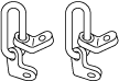 |
1: 49 C017 5A0
2: –
Engine support set
|
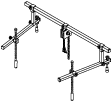 |
1: 49 L017 5A0
2: –
Support hanger
|
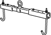 |
|
1: 49 S120 710
2: –
Coupling flange holder
|
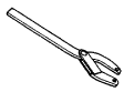 |
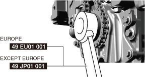
1:49 EU01 001
2: –
Holder [Europe]
|
 |
1:49 JP01 001
2: –
Holder [Except Europe]
|
|
Replacement Part
|
Cylinder head cover gasket
Quantity: 1
Location of use: Cylinder head cover
|
Front oil seal
Quantity: 1
Location of use: Engine front cover
|
O-ring
Quantity: 1
Location of use: Water pipe
|
|
Washer
Quantity: 2
Location of use: Engine front cover
|
—
|
—
|
Oil and Chemical Type
|
Silicone sealant
Type: TB1217D or equivalent
|
Coolant
Type: Recommended coolant
|
Operation After Replacing Timing Chain
1. After replacing the timing chain, perform the following procedure.
|
STEP
|
ACTION
|
PAGE/CONDITION
|
|
1
|
Perform KOEO self-test procedure.
|
|
|
2
|
Start the engine.
|
—
|
|
3
|
Verify that the check engine light does not illuminate.
|
—
|
|
4
|
Perform KOER self-test procedure.
|
|
|
5
|
Perform fuel injector injection amount correction.
|
|
|
6
|
Perform timing chain learning procedure.
|
|
|
7
|
Clear the DTCs.
|
|
|
8
|
Switch the ignition off.
|
—
|
|
9
|
Wait for 20 s or more.
|
—
|
Timing Chain Removal/Installation
-
Warning
-
• A hot engine can cause severe burns. Turn off the engine and wait until it is cool before servicing.
-
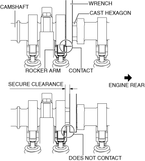
Caution
-
• When rotating the camshaft using a wrench on the cast hexagon, the wrench may contact the rocker arm and damage the rocker arm. To prevent damage to the rocker arm when holding the camshaft on the cast hexagon, use a wrench on the rear side of the engine as shown in the figure to secure a clearance between the cam.
-
Note
-
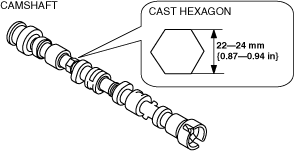
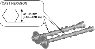
• Width at the cast hexagon of the camshaft is
22—24 mm {0.87—0.94 in}.
Fuel injector (2pin type)
Fuel injector (6pin type)
1. Disconnect the negative battery terminal. (See NEGATIVE BATTERY TERMINAL DISCONNECTION/CONNECTION.)
2. Remove the engine cover. (See ENGINE COVER REMOVAL/INSTALLATION [SKYACTIV-D 2.2].)
3. Remove the front under cover No.2. (See FRONT UNDER COVER No.2 REMOVAL/INSTALLATION.)
4. Remove the front splash shield (RH). (See SPLASH SHIELD REMOVAL/INSTALLATION.)
5. Remove the drive belt. (See DRIVE BELT REMOVAL/INSTALLATION [SKYACTIV-D 2.2].)
6. Remove the drive belt auto tensioner. (See DRIVE BELT AUTO TENSIONER REMOVAL/INSTALLATION [SKYACTIV-D 2.2].)
7. Drain the engine oil. (See ENGINE OIL REPLACEMENT [SKYACTIV-D 2.2].)
8. Remove the oil pan. (See OIL PAN REMOVAL/INSTALLATION [SKYACTIV-D 2.2].)
9. Remove the fuel injectors. (See FUEL INJECTOR REMOVAL/INSTALLATION [SKYACTIV-D 2.2].)
10. Drain the engine coolant. (See ENGINE COOLANT REPLACEMENT [SKYACTIV-D 2.2].)
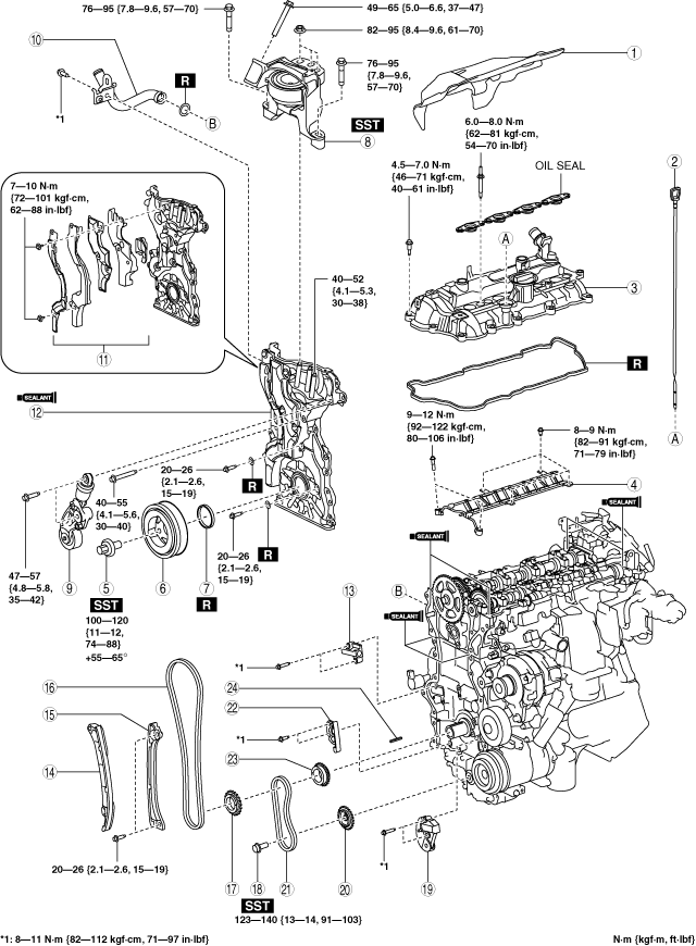
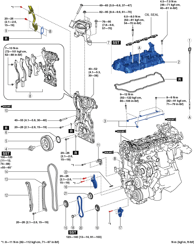
11. Remove in the order indicated in the table.
12. Install in the reverse order of removal.
13. Refill with the specified type and amount of the engine oil. (See ENGINE OIL REPLACEMENT [SKYACTIV-D 2.2].)
14. Refill the engine coolant. (See ENGINE COOLANT REPLACEMENT [SKYACTIV-D 2.2].)
15. Inspect for engine coolant leakage. (See ENGINE COOLANT LEAKAGE INSPECTION [SKYACTIV-D 2.2].)
16. If the timing chain is replaced, perform “Operation After Replacing Timing Chain”. (See Operation After Replacing Timing Chain.)
17. Start the engine and inspect the following:
-
• Leakage of engine oil.
• Runout and contact of pulley and belt.
Fuel injector (2pin type)
|
1
|
Insulator
|
|
2
|
Dipstick
|
|
3
|
Cylinder head cover
|
|
4
|
Oil shower pipe
|
|
5
|
Crankshaft pulley lock bolt
|
|
6
|
Crankshaft pulley
|
|
7
|
Front oil seal
|
|
8
|
No.3 engine mount
|
|
9
|
Drive belt auto tensioner
|
|
10
|
Water pipe
|
|
11
|
Noise suppression cover (No.1), noise suppression cover (No.2), seal rubber
|
|
12
|
Engine front cover
|
|
13
|
Timing chain tensioner
|
|
14
|
Timing chain tensioner arm
|
|
15
|
Timing chain guide
|
|
16
|
Timing chain
|
|
17
|
Crankshaft sprocket
|
|
18
|
Oil pump driven sprocket installation bolt
|
|
19
|
Oil pump chain tensioner
|
|
20
|
Oil pump driven sprocket
|
|
21
|
Oil pump chain
|
|
22
|
Oil pump chain guide
|
|
23
|
Oil pump drive sprocket
|
|
24
|
Key
|
Fuel injector (6pin type)
|
1
|
Dipstick
|
|
2
|
Cylinder head cover
|
|
3
|
Oil shower pipe
|
|
4
|
Crankshaft pulley lock bolt
|
|
5
|
Crankshaft pulley
|
|
6
|
Front oil seal
|
|
7
|
No.3 engine mount
|
|
8
|
Noise suppression cover (No.1), noise suppression cover (No.2), seal rubber
|
|
9
|
Water pipe
|
|
10
|
Engine front cover
|
|
11
|
Timing chain tensioner
|
|
12
|
Timing chain tensioner arm
|
|
13
|
Timing chain guide
|
|
14
|
Timing chain
|
|
15
|
Crankshaft sprocket
|
|
16
|
Oil pump chain tensioner No.2
|
|
17
|
Oil pump chain tensioner No.1
|
|
18
|
Oil pump driven sprocket installation bolt
|
|
19
|
Oil pump driven sprocket
|
|
20
|
Oil pump chain
|
|
21
|
Oil pump drive sprocket
|
|
22
|
Key
|
Cylinder head cover removal note
1. Remove the fuel feed pipe. (See SUPPLY PUMP REMOVAL/INSTALLATION [SKYACTIV-D 2.2].)
2. Remove the injection pipe (supply pump side). (See INJECTION PIPE REMOVAL/INSTALLATION [SKYACTIV-D 2.2].)
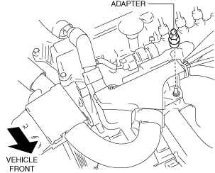
3. Set the wiring harness and ground cable aside using the following procedure:
- (1) Remove the adapter shown in the figure.
-
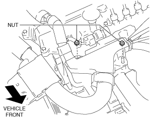
- (2) Remove the nuts shown in the figure.
-
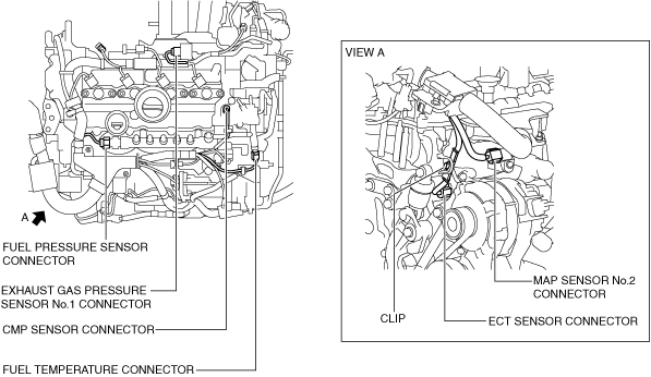
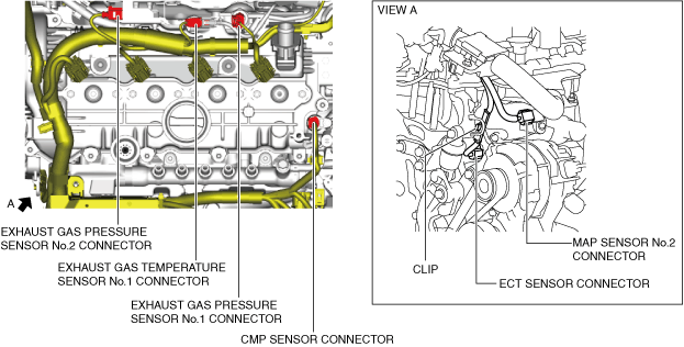
- (3) Disconnect the connectors and clip shown in the figure.
-
Fuel injector (2pin type)
Fuel injector (6pin type)
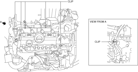
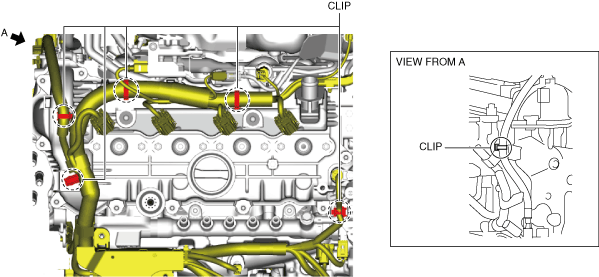
- (4) Remove the clips shown in the figure.
-
Fuel injector (2pin type)
Fuel injector (6pin type)
4. Set the exhaust gas temperature sensor No.1 bracket out of the way.
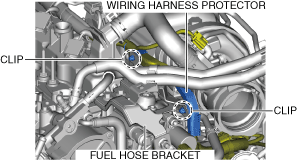
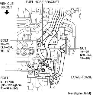
5. Set the lower case and fuel hose bracket aside using the following procedure:
- (1) Disconnect the vacuum hose from the vacuum pump.
-
- (2) Remove the fuel return hose No.4. (See COMMON RAIL REMOVAL/INSTALLATION [SKYACTIV-D 2.2].)
-
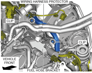
- (3) Remove the wiring harness protector from the fuel hose bracket.
-
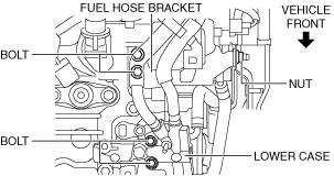
- (4) Remove the bolts and nut shown in the figure.
-
- (5) Set the lower case and the fuel hose bracket aside to the left side of the vehicle with the fuel main hose and return hose No.1 connected.
-
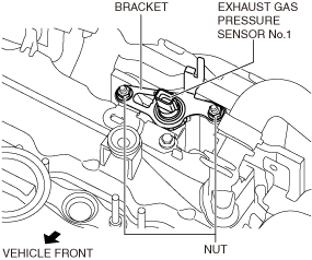
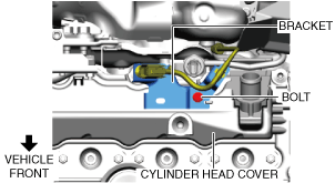
6. Set the exhaust gas pressure sensor No.1 aside using the following procedure: (Fuel injector (2pin type))
- (1) Remove the bracket shown in the figure.
-
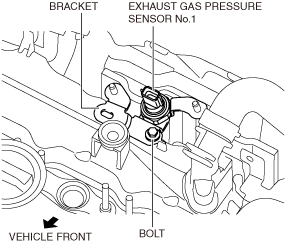
- (2) Remove the bracket shown in the figure.
-
- (3) Set aside the exhaust gas pressure sensor No.1 to the vehicle rear.
-
7. Remove the cylinder head cover.
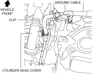
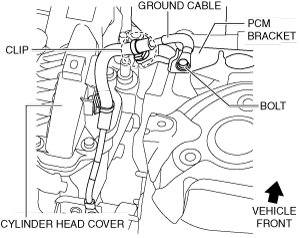
No.3 engine mount removal note
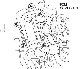
1. Remove the clip and bolt shown in the figure and set the ground cable aside.
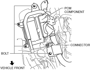
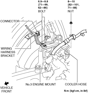
2. Remove the bolts and connector shown in the figure and set the PCM component aside with the PCM connector connected.
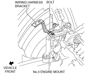
3. Set the connector and cooler hose shown in the figure aside and remove the wiring harness bracket. (Fuel injector (2pin type))
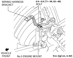
4. Remove the wiring harness bracket. (Fuel injector (6pin type))
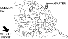
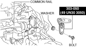
5. Remove the adapter shown in the figure.
6. Install the SST to the position shown in the figure using the following bolt and washer.
-
Bolt: part number 99794 1025 or an M10 x 1.25, length 25 mm {0.98 in}
-
Washer: approx. 3 mm {0.1 in} thickness
-
Tightening torque
-
38—51 N·m {3.9—5.2 kgf·m, 29—37 ft·lbf}
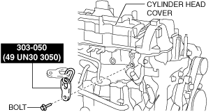
7. Install the SST to the position shown in the figure using the following bolt.
-
Bolt: part number 99794 1025 or an M10 x 1.25, length 25 mm {0.98 in}
-
Tightening torque
-
38—51 N·m {3.9—5.2 kgf·m, 29—37 ft·lbf}
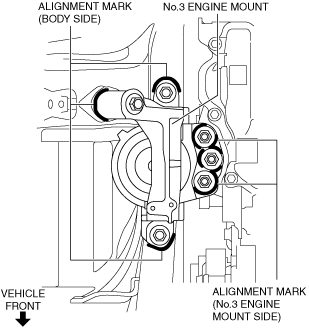
-
Caution
-
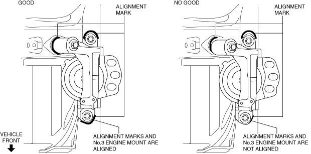
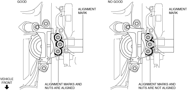
• Slots have been adopted for the No.3 engine mount installation holes. If the No.3 engine mount is deviated from the original position when installing the No.3 engine mount, engine noise or vibration could increase. Before removing the No.3 engine mount, place alignment marks on the No.3 engine mount and body so that they can be assembled to the same positions as before removal.
8. Place alignment marks on the locations shown in the figure so that they can be assembled to the same positions as before removal.
-
Note
-
• Paint so that the No.3 engine mount is framed on the body side and the outline of the nut is framed on the No.3 engine mount side.
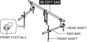
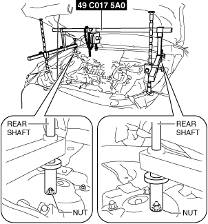
9. Install the SST using the following procedures.
-
Caution
-
• Refer to the SST instruction manual for the basic handing procedure.
-
Note
-
• Install front feet No. 2 to the left and right front shafts of the
SST.
- (1) Protect the positions shown in the figure using tape.
-
- (2) As shown in the figure, set the rear shafts of the SST to the left and right shock absorber nuts.
-
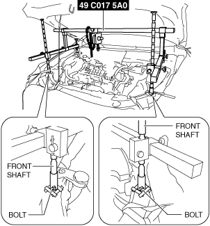
- (3) As shown in the figure, set the front shafts of the SST to the left and right bolts.
-
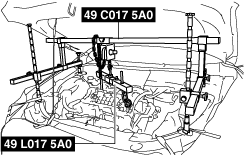
- (4) Install the SST (49 L017 5A0) to the SST (49 C017 5A0) as shown in the figure.
-
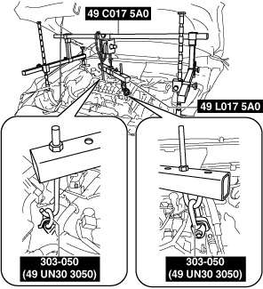
- (5) Install the SST (49 L017 5A0) to the SST (49 UN30 3050) with the hook of the SST (49 L017 5A0) facing outward.
-
- (6) Adjust the height of the left and right side bars so that they are leveled, then tighten each part of the SST.
-
- (7) Apply tension to the chain to secure the engine.
-
10. Remove the No.3 engine mount.
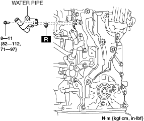
Water pipe removal note (Fuel injector (2pin type))
1. Remove the water pipe with the water hose connected and set it aside out of the way.
Noise suppression cover (No.1), noise suppression cover (No.2), seal rubber removal note (Fuel injector (2pin type))
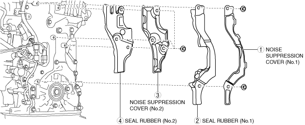
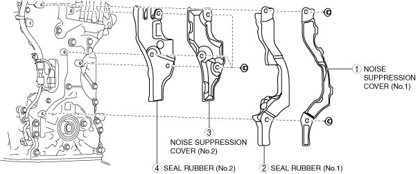
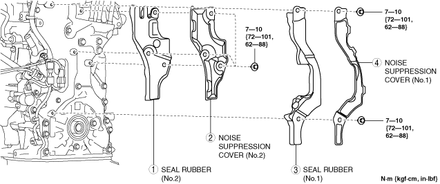
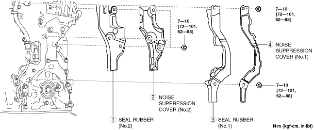
1. Remove the noise suppression covers and seal rubbers in the order shown in the figure.
2. Remove the connectors shown in the figure and set the wiring harness aside.
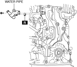
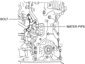
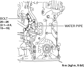
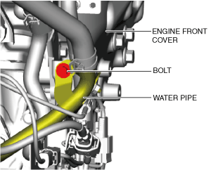
3. Remove the water pipe installation bolt shown in the figure.
4. Remove the connectors, clip, and bolts shown in the figure and set the wiring harness and wiring harness bracket aside.
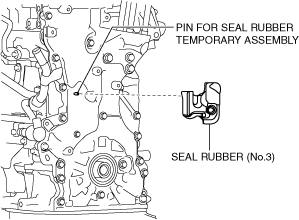
5. Remove the seal rubber (No.3) shown in the figure.
Noise suppression cover (No.1), noise suppression cover (No.2), seal rubber removal note (Fuel injector (6pin type))
1. Remove the noise suppression covers and seal rubbers in the order shown in the figure.
2. Remove the water pipe installation bolt.
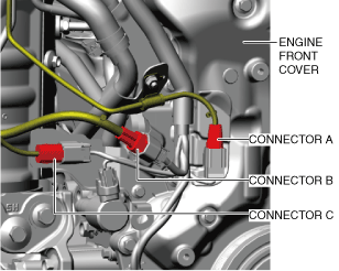
3. Disconnect the connector shown in the figure.
-
• Connector A: Exhaust gas temperature sensor No.2 connector
• Connector B: A/F sensor connector
• Connector C: Exhaust gas temperature sensor No.3 connector
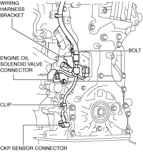
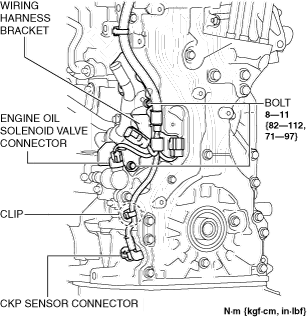
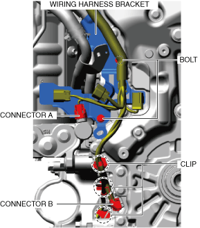
4. Remove the connectors, clips, and bolts shown in the figure and set the wiring harness and wiring harness bracket aside.
-
• Connector A: Engine oil solenoid valve connector
• Connector B: CKP sensor connector
5. Remove the seal rubber (No.3) shown in the figure.
Engine front cover removal note
1. Remove the engine front cover installation bolt.
-
Caution
-
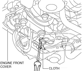
• Do not apply excessive force to the screwdriver. Otherwise, the engine front cover could be damaged.
• Be careful not to scratch or damage the seal surface. Otherwise, it could cause oil leakage.
2. Using a screwdriver wrapped in a rag, peel the sealant away a little at a time, and remove the engine front cover.
Timing chain removal note
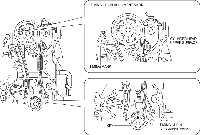
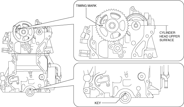
1. Rotate the crankshaft clockwise to adjust the timing marks and the key position as shown in the figure, and set cylinder No.1 at top dead center (TDC).
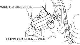
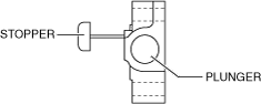
2. Loosen the timing chain tensioner using the following procedure:
- (1) Insert a wire with an approx. diameter of 1.4 mm {0.055 in} or a paper clip into the body hole of the timing chain tensioner.
-
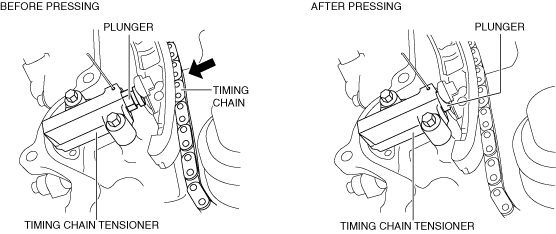
- (2) Press the timing chain in the direction of the arrow and press on the plunger of the timing chain tensioner.
-
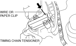
- (3) Press the wire or paper clip set in Step 1 further with the plunger pressed.
-
-
Note
-
• The wire or paper clip secures the plunger, and the tension can be released.
3. Remove the timing chain tensioner and timing chain tensioner arm.
4. Remove the timing chain guide.
5. Remove the timing chain and crankshaft sprocket as a single unit.
Oil pump chain removal note (Fuel injector (2pin type))
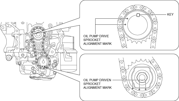
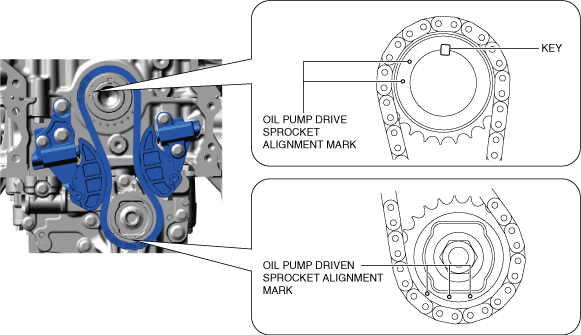
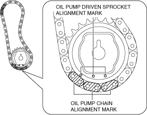
1. Verify that the oil pump driven sprocket alignment marks and key are aligned to the positions shown in the figure.
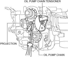
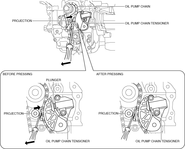
2. Set a cloth wrapped flathead screwdriver in the gap between the lower cylinder block projection and the oil pump chain as shown in the figure.
3. Move the screwdriver in the direction of the arrow and press the oil pump chain, and then press on the plunger of the oil pump chain tensioner.
4. Insert a wire with an approx. diameter of 1.4 mm {0.055 in} or a paper clip into the body hole of the oil pump chain tensioner with the plunger pressed.
-
Note
-
• The wire or paper clip secures the plunger, and the tension can be released.
5. Remove the oil pump chain tensioner.
6. Remove the oil pump driven sprocket installation bolt using the following procedure.
- (1) Lock the oil pump driven sprocket against rotation using the SST.
-
- (2) Remove the oil pump driven sprocket installation bolt.
-
7. Remove the oil pump chain and oil pump driven sprocket as a single unit.
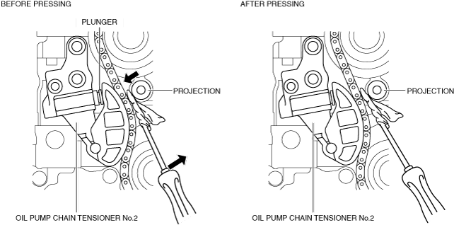
Oil pump chain removal note (Fuel injector (6pin type))
1. Verify that the oil pump driven sprocket alignment marks and key are aligned to the positions shown in the figure.
2. Release the tension on oil pump chain using the following procedure.
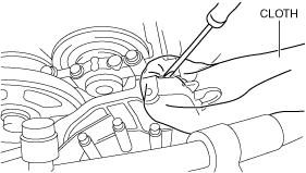
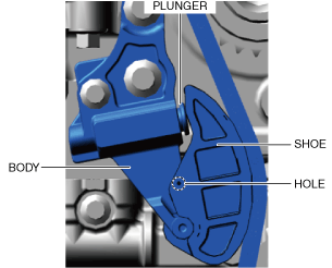
- (1) Press in the plunger of oil pump chain tensioner No.2 as shown in the figure using a screwdriver wrapped in a cloth.
-
- (2) Insert a wire or paper clip into the shoe hole with the plunger pressed in.
-
-
Note
-
• When inserting a wire or paper clip, the shoe is fixed with the plunger pressed in.
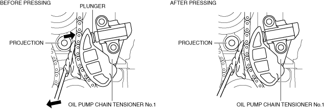
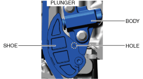
- (3) Press in the plunger of oil pump chain tensioner No.1 as shown in the figure using a screwdriver wrapped in a cloth.
-
- (4) Insert a wire or paper clip into the shoe hole with the plunger pressed in.
-
-
Note
-
• When inserting a wire or paper clip, the shoe is fixed with the plunger pressed in.
3. Remove the oil pump chain tensioner No.1 and No.2.
4. Remove the oil pump driven sprocket installation bolt using the following procedure.
- (1) Lock the oil pump driven sprocket against rotation using the SST.
-
- (2) Remove the oil pump driven sprocket installation bolt.
-
5. Remove the oil pump chain and oil pump driven sprocket as a single unit.
Oil pump chain installation note
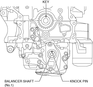
1. Verify that the key and knock pin are aligned to the positions shown in the figure.
-
• If they are not in the positions shown in the figure, rotate the crankshaft and balancer shaft (No.1) to set cylinder No.1 to top dead center (TDC).
-
Note
-
• When rotating the balancer shaft (No.1), temporarily assemble the oil pump driven sprocket and rotate while holding the sprocket with a hand.
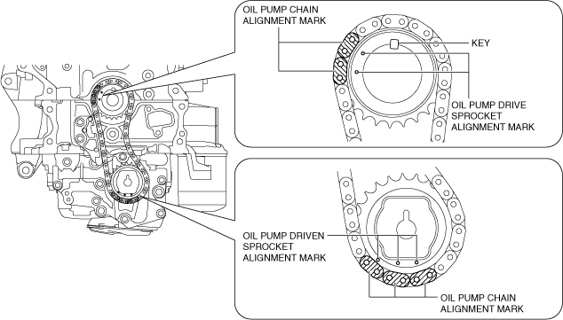
2. Align the oil pump chain alignment marks with the oil pump driven sprocket alignment marks.
3. Install the oil pump chain and oil pump driven sprocket as a single unit while aligning the alignment marks on each sprocket and oil pump chain as shown in the figure.
4. Temporarily tighten the oil pump driven sprocket installation bolt.
5. Install the oil pump chain tensioner. (Fuel injector (2pin type))
-
Tightening torque
-
8—11 N·m {82—112 kgf·cm, 71—97 in·lbf}
-
Caution
-
• At this stage, do not remove the wire or paper clip installed to the oil pump chain tensioner.
6. Install the oil pump chain tensioner No.1. (Fuel injector (6pin type))
-
Tightening torque
-
8—11 N·m {82—112 kgf·cm, 71—97 in·lbf}
-
Caution
-
• At this stage, do not remove the wire or paper clip installed to the oil pump chain tensioner.
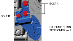
7. Install the oil pump chain tensioner No.2. (Fuel injector (6pin type))
-
Tightening torque
-
Bolt A : 20—26 N·m {2.1—2.6 kgf·m, 15—19 ft·lbf}
Bolt B : 8—11 N·m {82—112 kgf·cm, 71—97 in·lbf}
-
Caution
-
• At this stage, do not remove the wire or paper clip installed to the oil pump chain tensioner.
8. Tighten the oil pump driven sprocket installation bolt using the following procedure.
- (1) Lock the oil pump driven sprocket against rotation using the SST.
-
- (2) Tighten the oil pump driven sprocket installation bolt.
-
-
Tightening torque
-
123—140 N·m {13—14 kgf·m, 91—103 ft·lbf}
9. Remove the wire or paper clip installed to the oil pump chain tensioner and apply tension to the oil pump chain.
-
• If a new oil pump chain tensioner is used, remove the installed stopper.
Timing chain installation note
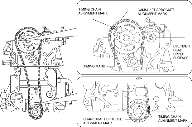
1. Verify that the timing marks and the key are aligned to the position shown in the figure.
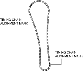
2. Align the timing chain alignment mark with the crankshaft sprocket alignment mark.
-
Note
-
• There are two timing chain alignment marks as shown in the figure. When assembling the timing chain and crankshaft sprocket, either timing chain alignment mark can be used.
3. Install the timing chain and crankshaft sprocket as a single unit while aligning the marks on each sprocket and the timing chain as shown in the figure.
4. Install the timing chain guide.
-
Tightening torque
-
20—26 N·m {2.1—2.6 kgf·m, 15—19 ft·lbf}
5. Install the timing chain tensioner arm.
6. Install the timing chain tensioner.
-
Tightening torque
-
8—11 N·m {82—112 kgf·cm, 71—97 in·lbf}
7. After installing the timing chain tensioner, remove the installed wire or paper clip, and then apply tension to the timing chain.
-
• If a new chain tensioner is used, remove the installed stopper.
8. Verify that there is no looseness in the timing chain, and re-verify that each sprocket is in the specified location.
9. Rotate the crankshaft clockwise two turns and inspect the valve timing.
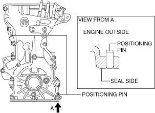
Engine front cover installation note
-
Note
-
• For a new engine front cover, the positioning pins in the
two locations shown in the figure project to the outside of the engine.
1. If the engine front cover is newly replaced, tap the positioning pins in the two locations to the seal surface side.
-
Caution
-
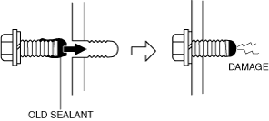
• If a bolt with sealant adhering to it is used, it could result in cracks in the cylinder head and cylinder block.
2. When reusing an engine front cover installation bolts, remove sealant adhering to the bolts.
-
Caution
-
• If oil, dirt and sealant remains on the sealant application area, the silicone sealant will not seal which will cause oil leakage.
3. Completely clean and remove any oil, dirt, sealant or other foreign matter that may be adhering to the engine front cover, cylinder head, and cylinder block.
-
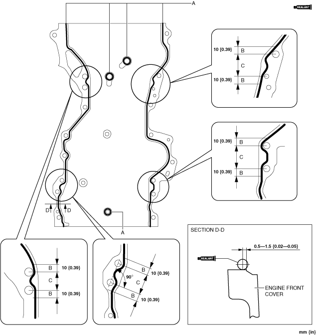
Caution
-
• Apply the silicon sealant in a single, unbroken line.
• To prevent silicone sealant from hardening, adhere the engine front cover and the cylinder block firmly within 10 min. after applying silicone sealant. After adhering them, tighten the installation bolts immediately.
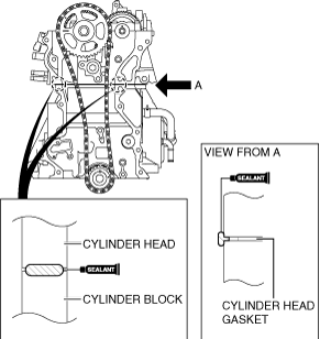
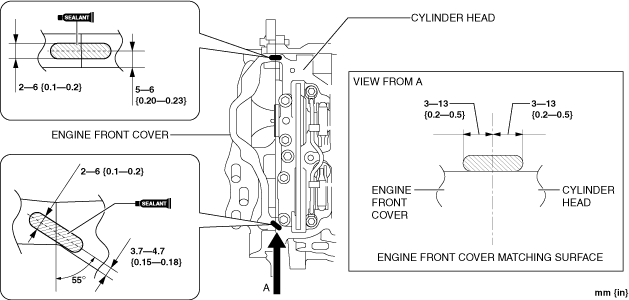
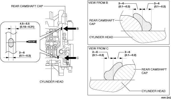
4. Apply silicone sealant (TB1217D or equivalent) to the engine front cover as shown in the figure.
-
Bead thickness
-
A: 2—6 mm {0.1—0.2 in}
B: 4—6 mm {0.16—0.23 in}
C: 4—8 mm {0.2—0.3 in}
-
Caution
-
• Apply the silicone sealant so that it goes into the cylinder head gasket.
5. Apply silicone sealant (TB1217D or equivalent) to the areas shown in the figure.
6. Install the engine front cover to the engine.
-
Caution
-
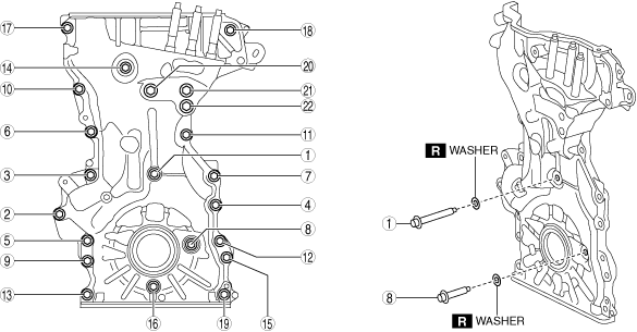
• For the number 1 and 8 bolts of the tightening order, install the bolts with new washers.
7. Tighten the engine front cover installation bolts in the order shown in the figure.
Tightening torque
|
Installation position
|
Tightening torque
|
|
1—19
|
20—26 N·m {2.1—2.6 kgf·m, 15—19 ft·lbf}
|
|
20—22
|
40—55 N·m {4.1—5.6 kgf·m, 30—40 ft·lbf}
|
-
Note
-
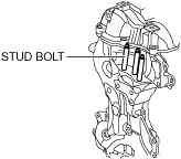
• Install stud bolts because there are no stud bolts installed on a new engine front cover.
• If the engine front cover is reused, tighten the stud bolts because they may have loosened.
8. Tighten the engine front cover stud bolts.
-
Tightening torque
-
40—52 N·m {4.1—5.3 kgf·m, 30—38 ft·lbf}
Noise suppression cover (No.1), noise suppression cover (No.2), seal rubber installation note (Fuel injector (2pin type))
1. Temporarily put the seal rubber (No.3) on the engine front cover.
2. Install the wiring harness and wiring harness bracket.
-
Note
-
• The seal rubber (No.3) can be fixed by installing the wiring harness bracket.
3. Tighten the water pipe installation bolt.
4. Connect the exhaust gas temperature sensor No.3 connector and A/F sensor connector.
-
Caution
-
• Be careful that the covers and seal rubbers do not get hung up on the noise suppression cover installation bolts.
5. Install the noise suppression covers and seal rubbers in the order shown in the figure.
Noise suppression cover (No.1), noise suppression cover (No.2), seal rubber installation note (Fuel injector (6pin type)
1. Temporarily put the seal rubber (No.3) on the engine front cover.
2. Connect the connectors and clips shown in the figure and install the wiring harness and wiring harness bracket.
-
Tightening torque
-
Bolt: 8—11 N·m {82—112 kgf·cm, 71—97 in·lbf}
-
• Connector A: Engine oil solenoid valve connector
• Connector B: CKP sensor connector
-
Note
-
• The seal rubber (No.3) can be fixed by installing the wiring harness bracket.
3. Connect the connector shown in the figure.
-
• Connector A: Exhaust gas temperature sensor No.2 connector
• Connector B: A/F sensor connector
• Connector C: Exhaust gas temperature sensor No.3 connector
4. Tighten the water pipe installation bolt.
-
Tightening torque
-
20—26 N·m {2.1—2.6 kgf·m, 15—19 ft·lbf}
-
Caution
-
• Be careful that the covers and seal rubbers do not get hung up on the noise suppression cover installation bolts.
5. Install the noise suppression covers and seal rubbers in the order shown in the figure.
Water pipe installation note (Fuel injector (2pin type))
-
Caution
-
• Do not apply oil (such as engine oil, ATF) to the O-ring. Otherwise, the O-ring could swell causing a seal malfunction.
• Install the water pipe so as not to damage the O-ring. Otherwise, it could cause a seal malfunction.
1. Install the water pipe following procedure:
- (1) Apply engine coolant to the O-ring.
-
- (2) Install the water pipe.
-
No.3 engine mount installation note
-
Caution
-
• If the No.3 engine mount is deviated from the original position when installing the No.3 engine mount, engine noise or vibration could increase. When installing the No.3 engine mount, align the alignment mark placed during removal and install it to the original position.
-
Note
-
• When replacing the No.3 engine mount, place a mark at the same position as the one placed before removal.
1. Temporarily tighten the No.3 engine mount installation bolts and nuts using the following procedure:
- (1) Align the alignment marks on the body side and No.3 engine mount, and temporarily tighten the bolts shown in the figure.
-
- (2) Temporarily tighten the nuts shown in the figure while aligning the alignment marks of the No.3 engine mount and nuts.
-
-
• If the alignment marks are deviated, align the alignment marks while slightly moving the engine and temporarily tighten the nuts.
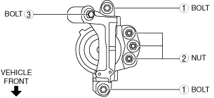
2. Tighten the No.3 engine mount installation bolts and nuts in the order as shown in the figure.
Tightening torque
|
Installation position
|
Tightening torque
|
|
1
|
76—95 N·m {7.8—9.6 kgf·m, 57—70 ft·lbf}
|
|
2
|
82—95 N·m {8.4—9.6 kgf·m, 61—70 ft·lbf}
|
|
3
|
49—65 N·m {5.0—6.6 kgf·m, 37—47 ft·lbf}
|
3. Remove the SST.
4. Install the wiring harness bracket, cooler hose and connector. (Fuel injector (2pin type))
5. Install the wiring harness bracket. (Fuel injector (6pin type))
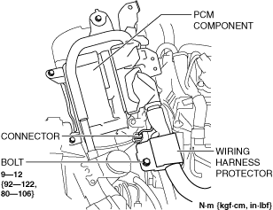
6. Install the PCM component using the following procedure:
- (1) Install the wiring harness protector and connector.
-
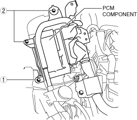
- (2) Temporarily tighten the bolt shown in the figure.
-
- (3) Tighten the PCM component installation bolts in the order shown in the figure.
-
-
Tightening torque
-
9—10 N·m {92—101 kgf·cm, 80—88 in·lbf}
7. Install the ground cable to the PCM bracket.
-
Tightening torque
-
9—12 N·m {92—122 kgf·cm, 80—106 in·lbf}
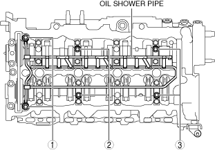
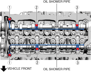
Oil shower pipe installation note
1. Install the oil shower pipe in the order shown in the figure.
Fuel injector (2pin type)
Fuel injector (6pin type)
Tightening torque
|
Installation position
|
Tightening torque
|
|
1
|
9—12 N·m {92—122 kgf·cm, 80—106 in·lbf}
|
|
2, 3
|
8.0—9.0 N·m {82—91 kgf·cm, 71—79 in·lbf}
|
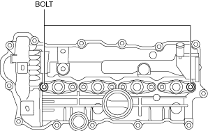
Cylinder head cover installation note
-
Caution
-
• To assure the sealing performance of the cylinder head cover, be careful of the following:
-
― Verify that the cylinder head cover gasket is inserted into the cylinder head cover groove and install the cylinder head cover.
― Completely clean and remove any oil, dirt, sealant or other foreign matter from the seal surface.
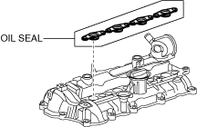
1. Install the cylinder head cover.
-
• Verify that the oil seal shown in the figure is not damage, and replace the oil seal if it is damaged.
2. Insert a new cylinder head cover gasket into the cylinder head cover groove.
-
Caution
-
• To prevent silicone sealant from hardening, adhere the cylinder head cover and the cylinder head firmly within 10 min. after applying silicone sealant. After adhering them, tighten the installation bolts immediately.
3. Apply silicone sealant (TB1217D or equivalent) to the areas shown in the figure.
Engine front side
Engine rear side
4. Install the cylinder head cover.
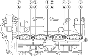
5. Tighten the cylinder head cover installation bolts using the following procedure:
- (1) Temporarily tighten the two bolts shown in the figure.
-
- (2) Tighten installation bolts A in the order shown in the figure.
-
-
Tightening torque
-
6.0—8.0 N·m {62—81 kgf·cm, 54—70 in·lbf}
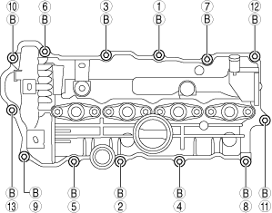
- (3) Tighten installation bolts B in the order shown in the figure.
-
-
Tightening torque
-
4.5—7.0 N·m {46—71 kgf·cm, 40—61 in·lbf}
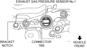
6. Install the exhaust gas pressure sensor No.1 using the following procedure: (Fuel injector (2pin type))
- (1) Return exhaust gas pressure sensor No.1 to its original position and install the bracket shown in the figure.
-
-
Tightening torque
-
8—11 N·m {82—112 kgf·cm, 71—97 in·lbf}
- (2) Install the bracket shown in the figure.
-
-
Tightening torque
-
8—11 N·m {82—112 kgf·cm, 71—97 in·lbf}
-
Note
-
• Align the tab of exhaust gas pressure sensor No.1 connector with the notch of the bracket.
7. Install the lower case and fuel hose bracket using the following procedure:
- (1) Return the lower case and the fuel hose bracket to their original positions.
-
- (2) Tighten the bolts and nut shown in the figure.
-
- (3) Install the wiring harness protector to the fuel hose bracket.
-
Fuel injector (2pin type)
Fuel injector (6pin type)
- (4) Install a new fuel return hose No.4. (See COMMON RAIL REMOVAL/INSTALLATION [SKYACTIV-D 2.2].)
-
- (5) Connect the vacuum hose to the vacuum pump.
-
8. Install the exhaust gas temperature sensor No.1 bracket.
-
Tightening torque
-
8—11 N·m {82—112 kgf·cm, 71—97 in·lbf}
9. Connect the wiring harness and ground cable using the following procedure:
- (1) Install the clips shown in the figure.
-
Fuel injector (2pin type)
Fuel injector (6pin type)
- (2) Connect the connectors and clip shown in the figure.
-
Fuel injector (2pin type)
Fuel injector (6pin type)
- (3) Tighten the nuts shown in the figure.
-
-
Tightening torque
-
9—12 N·m {92—122 kgf·cm, 80—106 in·lbf}
- (4) Install the adapter shown in the figure.
-
-
Tightening torque
-
4.0—5.6 N·m {41—57 kgf·cm, 36—49 in·lbf}
10. Install the injection pipe (supply pump side). (See INJECTION PIPE REMOVAL/INSTALLATION [SKYACTIV-D 2.2].)
11. Install the fuel feed pipe. (See SUPPLY PUMP REMOVAL/INSTALLATION [SKYACTIV-D 2.2].)
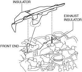
Insulator installation note (Fuel injector (2pin type))
1. Install the insulator using the following procedure.
- (1) Align the position so that the front end of the insulator is positioned at the front side of the vehicle from the exhaust insulator.
-
- (2) Insert the insulator until it contacts completely.
-