ac5wzw00008689
|
MANIFOLD ABSOLUTE PRESSURE (MAP) SENSOR REMOVAL/INSTALLATION [SKYACTIV-D 2.2]
id0140z7804300
MAP Sensor No.1 Removal/Installation (Fuel Injector (2Pin Type)
1. Disconnect the negative battery terminal. (See NEGATIVE BATTERY TERMINAL DISCONNECTION/CONNECTION.)
2. Remove the following parts:
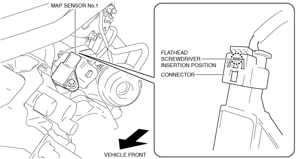
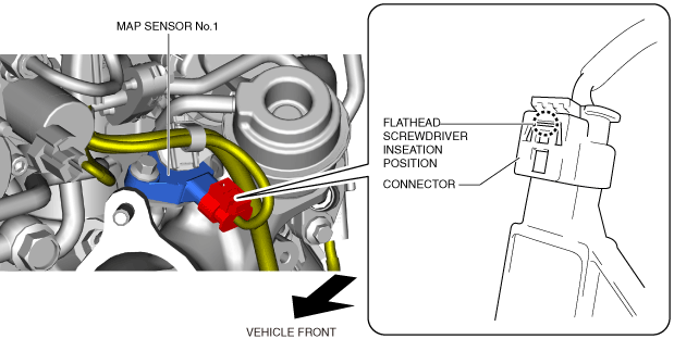
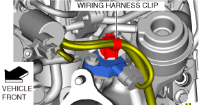
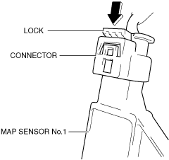
3. Disconnect the connector for the MAP sensor No.1 using the following procedure:
ac5wzw00008689
|
ac5wzw00008690
|
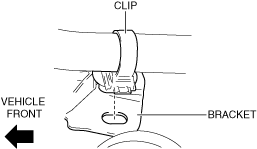
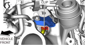
4. Remove the clip from the bracket.
ac5wzw00007830
|
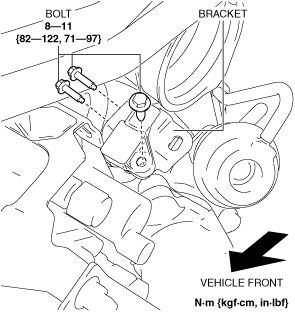
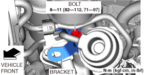
5. Remove the bolts from the bracket.
ac5wzw00005487
|
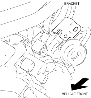
6. Remove the bracket.
ac5wzw00005488
|
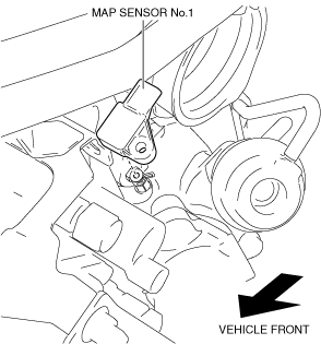
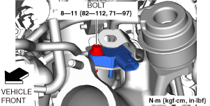
7. Remove the MAP sensor No.1. (See MAP sensor No.1 installation note.)
ac5wzw00008691
|
8. Install in the reverse order of removal.
MAP sensor No.1 installation note
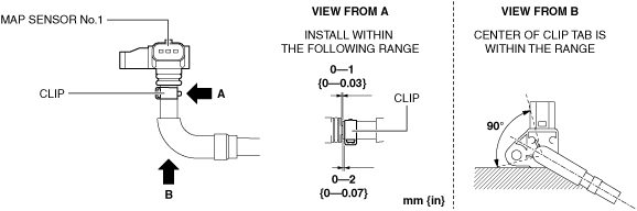
1. Install the MAP sensor No.1 shown in the figure.
ac5wzw00008692
|
MAP sensor No.1 connector connection note
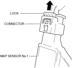
1. Connect the connector for the MAP sensor No.1 and press it in the lock direction of the arrow.
ac5wzw00008693
|
MAP Sensor No.1 Removal/Installation (Fuel Injector (6Pin Type)
1. Disconnect the negative battery terminal. (See NEGATIVE BATTERY TERMINAL DISCONNECTION/CONNECTION.)
2. Remove the following parts:
3. Disconnect the connector for the MAP sensor No.1 using the following procedure:
ac5wzw00012102
|
ac5wzw00012103
|
4. Remove the clip from the bracket.
ac5wzw00012104
|
5. Disconnect the hose from the MAP sensor No.1.
ac5wzw00012105
|
6. Remove the bracket.
ac5wzw00012106
|
7. Remove the MAP sensor No.1. (See MAP sensor No.1 installation note.)
ac5wzw00012107
|
8. Install in the reverse order of removal.
MAP sensor No.1 installation note
1. Install the MAP sensor No.1 shown in the figure.
ac5wzw00012108
|
MAP sensor No.1 connector connection note
1. Connect the connector for the MAP sensor No.1 and press it in the lock direction of the arrow.
ac5wzw00012109
|
MAP Sensor No.2 Removal/Installation
1. Disconnect the negative battery terminal. (See NEGATIVE BATTERY TERMINAL DISCONNECTION/CONNECTION.)
2. Remove the engine cover. (See ENGINE COVER REMOVAL/INSTALLATION [SKYACTIV-D 2.2].)
3. Remove the bolt, nuts and adapter.
ac5wzw00008694
|
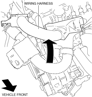
4. Set the wiring harness aside. (See Protector installation note.)
ac5wzw00004486
|
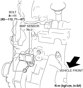
5. Disconnect the MAP sensor No.2 connector.
6. Remove the MAP sensor No.2.
ac5wzw00008695
|
7. Install in the reverse order of removal.
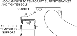
Protector installation note
1. Install a protector shown in the figure.
ac5wzw00008696
|